Table of Contents
Advertisement
Advertisement
Table of Contents

Related Manuals for Cobra MC 600Ci


Summary of Contents for Cobra MC 600Ci
- Page 2 6500 West Cortland Street, Chicago Illinois 60707 USA Cobra®, NightWatch®, Nothing Comes Close to a Cobra® and the snake design are registered trademarks of Cobra Electronics Corpora- tion, USA. Cobra Electronics CorporationTM, CobraMarineTM and iASAPTM are trademarks of Cobra Electronics Corporation, USA.
-
Page 3: Our Thank To You
CUSTOMER ASSISTANCE INFORMATION Should you encounter any problems with this product, or not understand its many features, please refer to this Owner’s Manual. If you require further assistance after reading this Owner’s Manual, Cobra Electronics Corporation offers the following customer assistance services: For Assistance in the U.S.A... -
Page 4: Control And Indicators
Control and Indicators SOFTWARE BUTTONS FUNCTIONALITY The software buttons have different functions according to the modes of operation: their labels for the current functions, are shown on the screen right above the buttons. They can also be used like FM radio preset buttons to save quick access to your favorite pages. -
Page 5: Software Features
Software Features and Technical Specifications SOFTWARE FEATURES Detailed Base Map Included 3D Mapping (view charts in either top down or new 3D perspective modes) 12 Channel WAAS GPS with iASAP Sunlight and NightWatch Easy surfing among the available pages (Data, Highway, Sun & Moon, Split, GPS Status, System and Welcome pages) Fish Finder and Combo pages DSC Calling integration... -
Page 6: Warnings And Cautions
Warnings and Cautions WARNINGS AND CAUTIONS Before using your CobraMarine general precautions and warnings. Electronic charts displayed by the chartplotter are believed to be accurate and reliable, but they are not intended to replace official charts which should remain your main reference for all the matters related to the execution of a safe navigation. -
Page 7: What Is In The Box
Included in This Package and C-MAP C-CARD WHAT IS IN THE BOX? When the package containing the chartplotter is first opened, please check it for the following contents (if any parts are missing contact the dealer the chartplotter was purchased from): CobraMarine MC 600C chartplotter Power Data Cable... -
Page 8: Table Of Contents
Table of Contents MANUAL ORGANIZATION 1.1. TABLE OF CONTENTS INTRODUCTION ... A1 OUR THANK S TO YOU ... A1 CUSTOMER ASSISTANCE ... A1 CONTROL AND INDICATORS ... A2 SOFTWARE BUTTONS FUNCTIONALITY ... A2 SOFTWARE FEATURES ... A3 TECHNICAL SPECIFICATIONS ... A3 WARNINGS AND CAUTIONS ... - Page 9 Table of Contents 2.12. USING MOB ... 20 2.12.1. Inserting MOB ... 20 2.12.2. Deleting MOB ... 20 3. PAGE INFORMATION AND OPERATION ... 21 3.1. PAGE SELECTION AND PRESETS - SETUP ... 21 3.2. WELCOME PAGE ... 22 3.2.1. Operations ... 22 3.3.
- Page 10 Table of Contents 3.9. SPLIT MODE PAGE ... 44 3.9.1. Description ... 44 3.9.1.1. Available Layouts of SLIT MODE Page ... 44 3.9.1.2. Changing Data Options ... 44 3.9.1.3. Changing the size of windows ... 45 3.9.1.4. Changing the Screen Control ... 45 3.9.2.
- Page 11 Table of Contents 5.2.1. Display Settings ... 60 5.2.2. Chart Settings ... 61 5.2.2.1. Chart Presentation ... 61 5.2.2.2. Depth Presentation ... 63 5.2.2.3. Land Presentation ... 64 5.2.2.4. Advanced Chart Settings ... 64 5.2.3. General ... 67 5.2.4. Fish Finder Settings ... 67 5.2.4.1.
-
Page 12: General Operation
E Any menu operation and function activation in this Owner’s Manual is related to both MC 600Cx and MC 600Ci chartplotter models. Whenever it is necessary, a note has been inserted for the model with differences. -
Page 13: Alphanumeric Input Procedure
General Operation have activated the menu from the CHART Page (by pressing the MENU button) to select the option you want, “NUMBER OF DATA FIELDS” option, follow the procedure listed below: 1. Use the UP and DOWN CURSOR buttons to select the desired option, “NUMBER OF DATA FIELDS”. - Page 14 General Operation When the field is highlighted: 1. Use the R or L IGHT you would like to change. 2. Use the UP, DOWN, RIGHT or LEFT CURSOR buttons to step through the available characters until the desired character is highlighted. 3.
-
Page 15: Basic Operation
Switching On/Off BASIC OPERATION Refer to the foldout on the front cover to identify the various controls and indicators on your chartplotter. 2.1. SWITCHING ON/OFF Before powering On the chartplotter, check for the correct voltage (10-35 volt dc). 2.1.1 Switching On Press and hold the PWR button for one (1) second. -
Page 16: Definitions Of Selections
Initial Setup 2.2.1. Definitions of Selections This menu allows you to select some of the basic setup information the first time the chartplotter is powered On. This information can be changed at any time either from the SYSTEM Page (see Chapter 5) or by resetting the chartplotter. -
Page 17: Adjusting The Backlighting And Contrast
Initial Setup medium sea level unit among the available units. The default setting is Ft (Feet). Other options are Meters (Mt) and Flight Level (FL). “TIME REFERENCE” - Allows switching the Time Reference between UTC or Local. After entering the Local Time offset, your local time will be displayed. -
Page 18: Page Surfing
Backlight and Contrast Page Surfing 3. Wait or press the ENTER button to return to the chart screen with the new light levels retained. Continuously pressing the PWR button from this screen will toggle you through the available color palettes. 2.4. -
Page 19: Demo Mode
DEMO MODE, the GPS receiver is turned Off, so it is impossible to navigate. Do not try to navigate in a DEMO MODE. While the DEMO MODE is turned On, the GPS receiver is not active. All satellite signal strength bars are only a simulation and do not indicate any actual satellite signals. -
Page 20: Zoom
Moving and Zooming on Chart map Pointer to pan away from your present position and scroll to other map areas even outside of your current detail coverage. While panning past the edge of the current map display, the screen actively scrolls forward to provide continuous map coverage. -
Page 21: Changing Data Fields
Changing Data Fields 2.7.2. Change Data Fields Each data field present on a given page (no matter the number of data fields) can be customized to obtain the best navigational information. 1. Press the MENU button. The MAIN Menu will be activated. 2. -
Page 22: Available Data Options
Available Data Options Creating a User Point 2.7.3. Available Data Options All the available choices for the Data Fields are presented in the table below. Keep in mind that some of them are characteristic only to one specified page. The yellow bar on the right will scroll down as you move down the list. 2.8. -
Page 23: Creating A New Mark
Creating a Basic Route 4. Move the Pointer off the location to accept. 2.8.2. Creating a New Mark A Mark can be created at anytime. Marks are used for marking points outside of a Route. 1. Move the Pointer to the desired location on the chart. 2. -
Page 24: Using Goto
Using Goto and Find 2.10. USING GOTO The GOTO function allows instant plotting of course to selected target. After pressing the GOTO button on most of the pages, the sub-menu on a Pointer position appears and it is possible to choose beneath mentioned options: “GOTO POINTER”... -
Page 25: Using Mob
Using MOB 2.12. USING MOB If a person or object is lost overboard and you need to return to the location, use the MOB (Man OverBoard) function. This function enables you to simultaneously mark and set a course to a location for quick response to emergency situations. -
Page 26: Page Information And Operation
Page Selection and Presets PAGE INFORMATION AND OPERATION 3.1. PAGE SELECTION AND PRESETS - SETUP Any page can be turned ON or OFF using the following procedure: 1. Press the PAGE button several times to select “SYSTEM” and then press the ENTER button. -
Page 27: Welcome Page
Welcome Page 3.2. WELCOME PAGE The WELCOME Page is activated by default on Power On and appears after the GPS position lock. Use the WELCOME Page to go to the most commonly- used features on the chartplotter that are otherwise more difficult to access. All of the options in these large selection boxes are also available from other pages and selections. - Page 28 Welcome Page “DEMO MODE”: Links to a secondary set of selection boxes. The DEMO Mode is specified in further detail in Par. 2.5. “DAY OR NIGHTWATCH Nightwatch depending on what mode the display is in at the time of selection. The screen will be difficult to read if the chartplotter is in Nightwatch sun is to bright.
-
Page 29: Chart Only Page
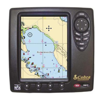
Chart Only Page 3.3. CHART ONLY PAGE The CHART Page is the main page of the chartplotter. From this page the user can select the desired map, get information about cartographic objects on the maps, see the vessel position, its direction and speed, place points (Marks, Waypoints), set a destination point and display additional features. -
Page 30: Operations On User Points
Chart Only Page 3.3.2.3. Operations on User Points Using the ENTER button we are able to create, edit and delete various User Points used during further navigation. Those advanced operations are explained in detail in Chapter 4. 3.3.2.4. Software Buttons The functional software buttons are activated when moving the Pointer with the CURSOR buttons. -
Page 31: Data Fields
Chart Only Page MAIN “STOP NAVIGATION”: Stops navigation to destination, if Target is set. “3D VIEW”: Changes from standard to 3D mode. This could also be used to choose viewing angle. “DYNAMIC NAV AIDS”: Turns ON or OFF the blinking lights on Nav-Aids. “NIGHT MODE”: Toggles the color setting in color pallets directly between the current daytime color pallet and night mode. -
Page 32: Data Page
Data Page 3.4. DATA PAGE Use the DATA Page to customize the data options described below. 3.4.1. Description The pictures below present the available DATA Page layouts with respect to displayed data fields. 3.4.2. Operations The main feature of the DATA Page is the ability to customize all data options according to a user’s requirements. -
Page 33: On Screen Instructions
Data Page 3.4.2.3. On Screen Instructions When first arriving at the page or after pressing the ENTER button, Screen Instructions will appear at the top of the page. The Screen Instructions are On by default and disappear after a few seconds. This option can be turned OFF for more advanced users. - Page 34 Data Page “SCREEN INSTRUCTIONS” at the top of the page are ON by default. This option allows the users to turn OFF these Screen Instructions once they are familiar with the features. “DEFAULT DISPLAY”: Changes the DATA Page that is the first displayed.
-
Page 35: Highway Page
Highway Page 3.5. HIGHWAY PAGE Whenever it is activated the HIGHWAY Page uses the most relevant navigation information to provide digital and graphical steering guidance to the destination. 3.5.1. Description The picture below shows the layout of the HIGHWAY Page with 4 data fields and a steering compass above the Horizon. -
Page 36: Available Layouts Of Highway Page
Highway Page 3.5.2.1. Available Layouts of HIGHWAY Page The data fields of the HIGHWAY Page can be customized to HIDE, 2 or 4 through the MENU button. By default the HIGHWAY Page is specified for 4 data fields and a Steering Compass added over the Horizon. It is possible to customize all data fields according to the user’s requirements. -
Page 37: Sun And Moon Page
Sun and Moon Page 3.6. SUN AND MOON PAGE The SUN and MOON Page presents a graphical chart that displays Tide station information in a 24-hour span starting at midnight. The choice of different dates and various Tide Stations all around the world is available. Tide data shown on this page comes from an optional C-CARD data. -
Page 38: Available Layouts Of Sun And Moon Page
Sun and Moon Page 3.6.2.1. Available Layouts of SUN and MOON Page. There is no possibility to change either the number of data fields nor their content. The default number of fields is 8 including: Latitude, Longitude, High Water Level, Low Water Level, Sunrise, Sunset, Date and Time. 3.6.2.2. -
Page 39: Changing The Date For The Tide Chart
Sun and Moon Page The result of your selection will be visible on a chart. An error message will appear if there are no Tide Stations in the immediate area. Use the Pointer to select a location closer to a Tide Station. 3.6.2.4. -
Page 40: Fish Finder Page
Fish Finder Page 3.7. FISH FINDER PAGE The FISH FINDER Page appears only when the Fish Finder device is available or a Demo Mode is active. The Fish Finder monitors the water column and delivers valuable information about school of fish and bottom structure. - Page 41 Fish Finder Page your transducer; the items on the right side of the screen are closer to you than those on the left. The correct interpretation of the Echogram allows retrieving useful information about what is under the boat. See the following Par.
-
Page 42: Understanding The Fish Finder Echogram
Fish Finder Page 3.7.1.1. Understanding the Fish Finder Echogram The main elements that can be easily distinguished into an Echogram are: Fish Fish is represented as arc because of the cone angle of the transducer. In fact as the boat passes over the fish the leading edge of the cone strikes the fish, causing a display pixel to be turned on. -
Page 43: Operations
Fish Finder Page Surface Clutter Appears like noise at the top of the screen extending many feet below the surface. It’s caused by many things, including air bubbles, bait fish, plankton and algae. Structure Generally, the term “structure” is used to identify objects like wrecks and weeds rising from the bottom. - Page 44 Fish Finder Page “PRESET MODE”: Applies the Fish Finder operating mode presets. “WHITE LINE”: Used to monitor how the Fish Finder device displays information about the nature of a bottom (soft or hard). The thin White Line indicates a softer bottom whereas a thick White Line indicates a harder bottom.
- Page 45 Fish Finder Page display. This selection is a personal preference. Select the option that gives you the clearest viewing in your weather conditions and viewing angle. “ALARMS”: Opens the Alarm Settings for Fish Finders within the System Menu. A full description of these alarms is in Par. 5.2.5.3. “FISH SYMBOLS”: Graphical representation of underwater suspended targets.
-
Page 46: Combo Mode Page
Combo Mode Page 3.8. COMBO MODE PAGE The COMBO MODE Page allows you to set vertical and horizontal combo screens to display CHART and FISH FINDER Pages simultaneously. 3.8.1. Description The pictures below represent different combinations of displayed combo screens. Each configuration can be activated from the MAIN Menu after pressing the MENU button. -
Page 47: Available Layouts Of Combo Mode Page
Combo Mode Page 3.8.2.2. Available Layouts of COMBO MODE Page The data fields in the COMBO MODE Page are the same as in the SPLIT MODE Page and can be customized to HIDE, 2 or 4 through the MENU button. By default the COMBO MODE is set to Hide data fields. 3.8.2.3 Changing Data Options The content of each data box can be adjusted to user’s requirements. -
Page 48: Screen Control
Combo Mode Page Press and hold the ENTER button for more than one (1) second to quickly enter the Adjust Split option. Adjust Split option will change the ratio for the two displayed Combo screens by approximately 1/3rd and 2/3rd of the screen. When changing the height of the water column, the history of the Fish Finder will be lost. -
Page 49: Split Mode Page
Split Mode Page 3.9. SPLIT MODE PAGE Vertical and horizontal split screens allows for 2 display modes to be displayed simultaneously. This page can be used with or without the optional CobraMarine Fish Finder connected. 3.9.1. Description These are some examples of available split mode options. These and more configuration options can be activated from the MAIN Menu after pressing the MENU button. -
Page 50: Changing The Size Of Windows
Split Mode Page customize data options follow the procedure described in Par. 2.7.2 Changing Data Fields. 3.9.1.3. Changing the size of windows See Par. 3.8.2.4 in the COMBO MODE Page section for detailed function description. 3.9.1.4. Changing the Screen Control The choice for Screen Control toggles the active window between the TOP, BOTTOM, RIGHT and LEFT. -
Page 51: Gps Page
GPS Page 3.10. GPS PAGE The GPS Page provides a visual reference of satellite acquisition, receiver status, and accuracy. This page only comes up during boot up until a GPS fix is achieved. It can be turned On in the SYSTEM Page, but it is Off by default, for typical Page surfing. -
Page 52: Menu
GPS Page 3.10.2. Menu The GPS Page has its own menu, which is used for setting satellite options. To access the MAIN Menu, press the MENU button: “RESTART GPS”: Initializes and restarts the GPS. “GPS SETUP”: Goes to the GPS Settings in the SYSTEM Page. “COM SETTINGS”: Goes to the COM Settings in the SYSTEM Page. -
Page 53: System Page
System Page 3.11. SYSTEM PAGE The SYSTEM Page includes selections for the various categories of Set-Up Info. 3.11.1. Description The picture below shows the layout of the SYSTEM Page with the main setting options for different functions. This section contains many settings that can be customized by the user but are usually not necessary. -
Page 54: Advanced Operation
Measure Function Advanced Waypoint Operations ADVANCED OPERATION 4.1. MEASURE FUNCTION The MEASURE Function allows you to measure the distance and bearing from one location to another. The starting point can either be the vessel location or the Pointer location on the chart. 1. -
Page 55: Moving A Waypoint
Waypoint and Route Operations 2. Press the D software button. ELETE 3. The Waypoint is deleted and a new line between previous and next Waypoint is shown. 4.2.2. Moving a Waypoint You can move any Waypoint in the Route to another location: 1. -
Page 56: Selecting Existing And Naming New Routes
Route Operations 4.3.1. Selecting existing and Naming new Routes To select the Route operations follow the procedure: 1. Press the MENU button from one of the CHART Pages, select “ROUTES” and press the ENTER button. 2. The Route table is shown on the screen. Use the UP or DOWN CURSOR button to select the desired row. -
Page 57: Using Track
Using Track 4.4. USING TRACK A very useful feature of the chartplotter, is the ability to store and display exactly where the boat has been. This feature, referred to as Tracking, can provide invaluable information about the effect of Tide and wind influence on the boat's progress as well as giving an indication of the helmsman's performance. -
Page 58: User Points List
User Points List greater than a defined distance); TIME (the chartplotter can store a fix after a defined time); AUTO (the software decides when storing a position, on the basis of the straight or curved Track). The default setting is Time. “DISTANCE”: When the Tracking function is On and the step unit is set to Distance, you can store a fix when the distance from its last stored position is greater than a defined distance. -
Page 59: User C-Card Operations
User C-CARD Operations bottom of a screen with the following options. Select the desired row and use these software buttons: “M ”: Moves the existed User Point. Shows the User Point on the chart in blue. Move the Pointer to the new desired location and press the ENTER button. -
Page 60: Saving File On User C-Card
User C-CARD Operations button otherwise). When completed, the message “OK” is shown. When a User C-CARD is formatted, all data saved on it will be deleted. 4.6.3. Saving file on User C-CARD The Save function copies the selected file from the internal memory of the chartplotter to the User C-CARD. -
Page 61: Info
Info 4.7. INFO When placing the Pointer above objects on the chart, information related to the objects nearby is shown. 4.7.1. Setting Automatic Info Automatic Info allows you to get the information on any cartographic object just by placing the Pointer on it. You can select your preferred level. This feature is ON by default. -
Page 62: Info Tree And Expanded Info Page
Info Current Predictions To see the picture press the MENU button when the object with a picture is highlighted. 4.7.4. Info Tree and Expanded Info page The upper side of the page contains the Info Tree and the Lower side contains the expanded information. -
Page 63: Pictures
Dynamic Nav-Aids Pictures Lights in the correct color based on boats position with all the Nav-Aids name displayed below the Nav-Aid symbol. This feature is ON by default. You can turn it OFF in the Advanced Chart Settings section of the SYSTEM Page. Only Nav-Aids that are within the nominal range of the vessel are lit. -
Page 64: Advanced Dsc For Vhf Radio With Nmea 0183 Output
DSC Calling 4.11.1. Advanced DSC for VHF Radio with NMEA 0183 Output The DSC CALLING Page can be selected using the PAGE button which is generally used to scroll through all available pages: this is possible only if the DSC CALLING Page is turned ON in the “PAGES ON/OFF” menu (see Par. 3.1 for more information). -
Page 65: System
System Page Display Settings SYSTEM PAGE SETTINGS 5.1. SCREEN SHOT AND DESCRIPTIONS 1. Press the PAGE button several times to select “SYSTEM” and press the ENTER button. The SYSTEM Page appears on the screen: 5.2. OPERATIONS BY SETTING GROUP After the SYSTEM Page is shown, use the CURSOR buttons to select the menu you want and press the ENTER button. -
Page 66: Chart Settings
Chart Settings the display. The chartplotter displays maps and screens in darker colors. It is also possible to go through the available color palettes by pressing the PWR button. See Par. 2.3. Press the button repeatedly to scroll through the options. “BACKLIGHTING TIMEOUT”: Sets the time value among 1, 3, 5, 10 MIN: after this time when no button is pressed, the screen and keyboard backlight is turned Off. - Page 67 Chart Settings may be projected in perspective mode during navigation. The upper side of the map is more compressed than the lower side, a wider map area is visible. The perspective view allows showing more chart information immediately ahead and around the Pointer. “COLOR PALETTE”: See previous Par.
-
Page 68: Depth Presentation
Chart Settings strength of the current changes throughout the day. “PORTS AND SERVICES”: Turns ON or OFF the displaying of the Ports and Services (areas along shore with facilities for mooring, downloading and uploading of ships, generally sheltered from waves and winds. Port installations are piers, wharves, pontoons, dry docks, cranes, etc). -
Page 69: Land Presentation
Chart Settings 5.2.2.3. Land Presentation To control the display on the map of the land based (terrestrial) features. After the CHART SETTINGS menu is shown: 1. Use the UP or DOWN CURSOR button to select “LAND PRESENTATION” and press the ENTER button. 2. - Page 70 Chart Settings “MIXING LEVELS”: When the map coverage at the current zoom level does not fill the entire screen, the chartplotter draws the rest of the map expanding the cartographic information read from, at most, two zoom levels above the current zoom level. For this reason the map is drawn three times: firstly it draws the two levels before the current level and then the current level.
- Page 71 Chart Settings “SCREEN AMPLIFIER”: The Screen Amplifier function automatically offsets the map on the screen so more open area is placed “ahead” of the vessel. “ORIENTATION RESOLUTION”: It is the angle you must turn before the map will rotate (defines the maximum variation of the reference angle after which the map changes its orientation).
-
Page 72: General
General “ATTENTION AREAS”: Turns ON or OFF the displaying of Attention Areas (areas in which special attention by the mariner is required, because of natural or man-made hazards, or sailing regulations and restrictions. Moreover a special symbol (!) is placed inside the area selecting On option. This is valid also for the categories: FISHING FACILITY, MARINE FARM/CULTURE, MILITARY PRACTICE AREA, RESTRICTED AREA, SEAPLANE LANDING AREA. -
Page 73: Display Settings
Fish Finder Settings 5.2.4.1. Display Settings To control the display settings of the video screen. After the FISH FINDER SETTINGS menu is shown: 1. Use the UP or DOWN CURSOR button to select “DISPLAY SETTINGS” and press the ENTER button. 2. -
Page 74: Transducer Settings
Fish Finder Settings the sensitivity may increase the clarity of the display. “NOISE TRESHOLD”: Helps filter unwanted noise from the chart. It can be turned from 0 (no noise filtering) to 5 (maximum noise filtering). “STC”: Sensitivity Time Constant: it is a time varying gain curve which attenuates the sonar receiver gain in shallow water, increasing the gain gradually as the depth increases. -
Page 75: Alarm Settings
Fish Finder Settings 2. Use the UP or DOWN CURSOR button to select the desired option and then press the ENTER button. The available options are listed below: “KEEL OFFSET”: Transducer depth offset from the surface. This makes it possible to measure depth from the surface or the lowest point of the keel instead of from the transducer's location. -
Page 76: Fish Alarms
Alarm Settings from a defined course by the set distance. “PROXIMITY ALARM”: Triggers an alarm to sound when the destination is reached. “DEPTH ALARM”: Triggers an alarm to sound when the received depth value (from the depth transducer) is lower than the set value. “GUARDIAN ALARM”: Verifies potential danger to navigation such as shallow water (depth areas), intertidal areas, land, rocks, obstructions and shoreline constructions. -
Page 77: Pages On/Off
(TD function allows converting GPS coordinates to Loran-C coordinates and vice versa, see TD in the Par. 9.1) and UTM (also see UTM in the Par. 9.1). “FIX DATUMS”: Sets the datum reference used by the GPS receiver connected to (or integrated in) the chartplotter so that the chartplotter... -
Page 78: Demo
Demo selected in the menu in order to match the position from the GPS with the position on the charts. You must know what datum reference is used by the GPS and set it in the Fix Datum option. “MAP DATUMS”: Allows selecting any Geodetic Datum reference from the over 100 available on the chartplotter. -
Page 79: Com Settings
Com Settings Another place to enter Demo is the Welcome Page (see Par. 3.2). 5.2.10. Com Settings Selects the proper format for the Port1/2 Input, Port1/2 Output, Port1/2 Output Sentences. Displays also the Cable Wiring page. Selects the Send/Receive Marks & Routes ports. After the COM SETTINGS menu is shown. Use the UP or DOWN CURSOR button to select the desired option and then press the ENTER button. -
Page 80: About
About 5.2.11. About To see details about the software and cartography data installed open the System Information page. ® Nothing Comes Close to a Cobra... -
Page 81: Installation
Chartplotter Dimensions C-CARD Inserting INSTALLATION 6.1. BASIC This chapter provides instructions for inserting and removing C-CARD procedure, and to assist in planning the installation of the chartplotter. 6.1.1. Chartplotter Dimensions 6.1.2. C-CARD Inserting and Removing A notch for removing the cover is available on the bottom. Hold the C-CARD by the long inclined side so that you can see the C-MAP the C-CARD into the slot;... -
Page 82: Chartplotter Installation And Removing
Chartplotter Installation Wiring and Connectors 6.1.3. Chartplotter Installation and Removing Bracket Installation The chartplotter can be mounted using the supplied bracket. Before installing ensure the area the chartplotter's bracket is mounted to is strong enough to support the weight of the chartplotter. After the desired location is found, attach the mounting base to the area using the supplied hardware. -
Page 83: Advanced
Advanced 6.2. ADVANCED The chartplotter has connectors that are used to connect the chartplotter to Power Supply, to the GPS WAAS Smart antenna, optional FISH FINDER and to NMEA devices. 6.2.1. External NMEA Connection 6.2.2. GPS Connection 6.2.3. Autopilot and Basic DSC VHF Connection Owner's Manual (on MC 600Cx with External GPS) -
Page 84: External Alarm Connection
GPS Antenna 6.2.4. External Alarm Connection 6.2.5. Fish Finder It is possible to connect an optional FISH FINDER device. For connections and operation see the related Owner’s Manual. 6.3. MOUNTING THE GPS ANTENNA The chartplotter is supplied with a 12 Channel WAAS GPS Smart antenna. This antenna is designed to be mounted on a base, installed on an extension or even flush mounted. -
Page 85: Antenna Flush Mounting
GPS Antenna when reconnecting the antenna cable to protect from water and corrosion. A terminal strip will also be provided for joining the wire after it is cut. 6.3.1. Antenna Flush Mounting Before drilling holes, it is recommended the antenna be positioned where the location is planned to be drilled, cable connected to the chartplotter and the chartplotter turned On to ensure a fix is received. -
Page 86: Maintenance
System Test MAINTENANCE This chapter gives information on routine maintenance and problem solving associated with the chartplotter. SYSTEM TEST If you have connected your position-finding device according to the instructions, and chosen the proper menu selection for your device, and are still having problems with your chartplotter, the extended auto-test should help determine the problem. -
Page 87: Optional Accessories
PC-PLANNER MF 2500 FISH FINDER OPTIONAL ACCESSORIES 8.1. PC-PLANNER C-MAP ’s PC-PLANNER software is designed to turn your home computer into a navigational planning tool. Using the same C-MAP use on your boat, it is possible to display all of your electronic charts in full color on your PC screen. -
Page 88: Arrival Time
Terms APPENDIX 9.1. TERMS ALT = Altitude Altitude of GPS Antenna on the medium sea level. Alter = Alternate Solution (TD Coordinates System) Parameter selected by the user that is applied in the conversion of TD values to geographical coordinates Lat/Lon. It defines which of the two possible solutions can be used. -
Page 89: Cultural Features
Terms horizontal direction of one terrestrial point from another referring to the North (True or Magnetic). It is often used to indicate the direction to follow to reach the destination. Chain (Loran-C GRI) The Loran chains are groups of transmitting stations that use timed radio pulse transmissions. - Page 90 Terms Depth Area It is the sea area included in the (user selectable) range of minimum and maximum depth limits. The selected depth area is uniformly filled with a predefined color. Depth Line (Also called Bathymetric Line) It is the imaginary line connecting points of equal water depth.
-
Page 91: Magnetic Deviation
Terms HDG = Heading The horizontal direction in which a ship actually points or heads in any moment (see also COG). HDOP = Horizontal Dilution Of Precision Parameter indicating the precision of the positioning system (GPS). The smaller HDOP value indicates higher position accurately. Landmarks Any prominent object such as monument, building, silo, tower, mast, ..., on land which can be used in determining a location or a direction. - Page 92 Terms Mark Reference point related to Pointer position. Typically it represents by an icon and label under Mark. Natural Features Any topographic feature formed by the action of natural processes: coastlines, relief, glaciers. NMEA-0183 The NMEA-0183 Data Interface Standard was developed by the National Marine Electronics Association of America.
- Page 93 Terms RTCM = Radio Technical Commission for Maritime Services The data format created by the Radio Technical Commission Maritime to transmit Differential GPS corrections. SNR = Signal to Noise Ratio Ratio between the magnitude of a radio signal and the magnitude of the noise (that is, the interferences).
- Page 94 Terms TRN = Turning Difference between COG and BRG. If COG is 80° and BRG is 75°, TRN is 5° Left. TTG = Time To Go Estimated time needed to reach your destination, based on your current speed and the distance to destination. TWD = True Wind Direction Direction of the Wind relative to a fixed point on the earth.
-
Page 95: Gps
Currently, the GPS constellation consists of 26 orbiting satellites (including 3 spares), but this number will increase in the future. The GPS receiver computes an accurate position by calculating the distance to the GPS satellites that orbit the earth. Signals are required from 3 satellites for two dimensional (2D) position calculation whilst 4 satellites are required for three dimensional (3D) position calculation. -
Page 96: Position Fixing Accuracy: Hdop
1. GPS satellites continuously transmit their own precise orbital data and the GPS receiver computes their locations by receiving this data. 2. In this receiving process, the GPS receiver measures very accurate distances to the satellites, using the "Spread Spectrum Modulation"... - Page 97 The index for position-fixing accuracy is called HDOP ("Horizontal Dilution Of Precision"). The smaller the HDOP value, the more accurately the position can be fixed. Owner's Manual...
-
Page 98: World City Time Zones
WORLD CITY TIMES ZONES 9.3. WORLD CITY TIME ZONES Longitudinal Zone E 172.50 to W 172.50 W 172.50 to W 157.50 W 157.50 to W 142.50 W 142.50 to W 127.50 W 127.50 to W 112.50 W 112.50 to W 097.50 W 097.50 to W 082.50 W 082.50 to W 067.50 W 067.50 to W 052.50... -
Page 99: Index
INDEX About ... 75 ACTIVATE SIMULATION ... 73 ACTIVE TRACK ... 52 adjust backlight ... 12 adjust contrast ... 12 Advanced Chart Settings ... 63, 64 ADVANCED CHART SETUP ... 26 ADVANCED DATA SETUP ... 26 Alarm Settings ... 70 ALARMS ... - Page 100 HEADING ... 73 HIGHT WATER/LOW WATER ... 32 HIGHWAY Page ... 30, 45 How GPS Works ... 90 INFO ... 56 Info Tree ... 57 Inserting a Waypoint ... 50 Inserting MOB ... 20 Inserting the C-CARD ... 76 installation ... 76 INTEREST POINTS ...
Need help?
Do you have a question about the MC 600Ci and is the answer not in the manual?
Questions and answers