Table of Contents
Advertisement
Quick Links
Advertisement
Table of Contents

Related Manuals for Signal Nebula 4 Series


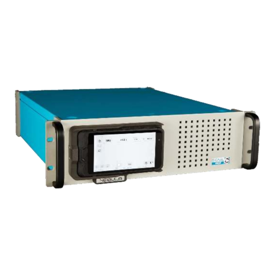
Summary of Contents for Signal Nebula 4 Series
- Page 1 Raising gas analysis to new levels www.signal-group.com P a g e | 1 of 26...
- Page 2 While we believe that the information and guidance given in this manual is correct, all parties must rely upon their own skill and judgment when making use of it. Signal Group Ltd. will not assume any liability to anyone for any loss or damage caused by any error or omission in the manual, whether such error or omission is the result of negligence or any other cause.
-
Page 3: Table Of Contents
Routine Maintenance ....................23 Introduction ......................23 Sample Filter ......................23 Routine Servicing ......................25 Schedule ....................... 25 Service Manual ..................... 25 Table of Figures ......................26 Table of Tables ......................26 www.signal-group.com P a g e | 3 of 26... -
Page 4: What's In The Box
• Sample filter key (MC/318011) • 9/16” Wrench • 7/16” Wrench • USB drive with related documents ‒ Analogue output connection cable – Signal Part No. MI/995 (Optional) ‒ Relay output connection cable – Signal Part No. MI/1020 (Optional) www.signal-group.com P a g e... - Page 5 ‒ Read all instructions prior to installing, operating, and servicing the product. ‒ If you do not understand any of the instructions, contact your Signal Group Ltd representative for clarification.
-
Page 6: Important Safety Instructions
‒ No part of a cylinder should be exposed to a temperature higher than 52°C (125°F), or a naked flame or incandescent material. ‒ Do not place cylinders where they could become part of an electric circuit. www.signal-group.com P a g e | 6 of 26... -
Page 7: Operation And Maintenance
Series 4 Operating Manual - Nebula Issue 1.00 Operation and Maintenance On leaving the Signal Group Ltd factory, this product conformed to all applicable safety directives. The operator must take care to follow the instructions given in this manual to preserve this condition. -
Page 8: Competent Personnel
Specialist knowledge of this instrumentation is a necessity for working with and on the unit. Authorised personnel for installing, operating, servicing, and maintaining the analyser are instructed and trained personnel of the operating company, Signal Group Ltd or their local representatives. -
Page 9: Quick-Start
Span – the unit will automatically open the span valve to begin measuring span gas. Sample – as Zero & Span but the unit will begin measuring Sample gas. Pause – Span, Zero and Sample Solenoids will all be closed. www.signal-group.com P a g e | 9 of 26... - Page 10 Front Panel Light codes Light Status Red Blink Heating Purple Loading Config File Yellow Standby Yellow Blink Purge Green Measurement Mode White No Config Red/Blue Alarm Blue Sleep www.signal-group.com P a g e | 10 of 26...
-
Page 11: Introduction
• On-board data logging; • 24VDC power supply. Signal is renowned for its ability to create instruments for special applications, so if the options above do not cover your specific requirements, then contact Signal or one of their local representatives to discuss your application further. -
Page 12: The Principle Of Tunable Diode Laser Spectrometry
It also has a heated exhaust pipe so that moisture build up does not occur and form aqueous ammonia in the outlet line. www.signal-group.com P a g e | 12 of 26... -
Page 13: Operation
‒ Humidity: In most cases, the analyser will only read a sample which has more than 5% H2O in the sample gas. If you intend to analyse gases under this level of humidity you will need to contact Signal Group LTD to configure the analyser for this, as it will not read accurately. -
Page 14: Start
‒ Ensure that the correct fuses are in place within the integrated IEC socket on the rear panel. ‒ Figure 2 below shows the rear panel layout of the NEBULA; ʺ SPAN ʺ ZERO ” SAMPLE INLET INLET INLET EXHAUST Figure 2: NEBULA pneumatic connections www.signal-group.com P a g e | 14 of 26... - Page 15 Care must be taken to avoid risk of burning or local build-up of sample gases. ‒ If desired, attach your chosen output cables (analogue/relays/etc) now. Preassembled cables can be purchased separately from Signal Group Ltd. Contact your local representative for details. Alternatively, see the Output Wiring section of this manual for connection information.
-
Page 16: Control
The diagram below is the recommended experimental setup for doing this: Figure 3: Nebula Calibration Schematic Signal Group LTD provide an external calibration unit with humidifying capabilities that will aid this process. Please contact the Sales team if this is something you require. Zero/Span Calibration ‒... - Page 17 ‒ There are many reasons that a stable reading would not be found. It is advisable to contact your local Signal Service representative for advice if this occurs. Measurement ‒ Once the unit is stable and fully calibrated, accurate measurements can be taken.
-
Page 18: Remote Control
‒ The following output relays are available depending on your selected option: • Standard IO – 3 (non-configurable) • Extended IO – 23 (20 configurable) • Special Extended IO – 35 (32 configurable) www.signal-group.com P a g e | 18 of 26... - Page 19 ‒ P level: λ60 = 0.1 x 10⁻⁶/operation. This value was measured at a switching frequency of 120 operations/min and the criterion of contact resistance is 100. This value may vary depending on the operating environment. Always double-check relay suitability under actual operating conditions www.signal-group.com P a g e | 19 of 26...
- Page 20 DIO6 LighBlue/Brown LightBlue/Black DIO14 Red/Black White DIO7 Gray/Brown LightGreen/Gray DIO15 Brown/White Pink DIO8 Black LightGreen/Black DIO16 Brown/Black Table 3 : Relay wiring table - Colours refer to Signal output cable MI/1020 www.signal-group.com P a g e | 20 of 26...
- Page 21 Orange White DIO6 Purple Orange DIO14 White DIO7 Purple DIO15 Brown Grey DIO8 Blue Brown DIO16 Black Table 4 : Relay wiring table - Colours refer to Signal output cable MI/996 www.signal-group.com P a g e | 21 of 26...
- Page 22 Blue White Violet Black White Red/Blue Orange Grey/Pink White White/Pink Yellow Brown/Green White White/Green Green Grey/Brown White White/Yellow Blue White/Grey White Yellow/Brown Purple Pink/Brown Table 5 : Chart Output Pinout Colour www.signal-group.com P a g e | 22 of 26...
-
Page 23: Routine Maintenance
Dirty Filters may contain corrosive compounds. Use gloves. Obey local safety measures. Signal recommends and supplies PTFE filters (Part number FILT/023) for use as internal Sample filter in all measurement instruments. These PTFE filters may be cleaned and re-used. Glass fibre filters are not recommended for use in our heated analysers. They can be damaged during installation into the heated manifold and fibres can become detached and block critical sample paths. - Page 24 • Re-assemble the filter cap to the analyser using the reverse procedure and reconnect the sample line. New filter elements are available from Signal with part number FILT/023. NOTE: If you did not purchase a spares kit with the analyser, consider purchasing one now.
-
Page 25: Routine Servicing
The analyser requires regular servicing to maintain its accuracy and operational status. Servicing should be carried out by a qualified service engineer with electrical and pneumatic experience. If you do not have these in-house skills, contact your local Signal representative who will be pleased to assist you. -
Page 26: Table Of Figures
Table 1 : Document history table ................... 1 Table 2 : Quick-start setup ....................9 Table 3 : Relay wiring table - Colours refer to Signal output cable MI/1020 ......20 Table 4 : Relay wiring table - Colours refer to Signal output cable MI/996 ......21 Table 5 : Chart Output Pinout Colour ..................
Need help?
Do you have a question about the Nebula 4 Series and is the answer not in the manual?
Questions and answers