Table of Contents
Advertisement
Available languages
Available languages
Quick Links
LIFTING TOWERS
AT
AT-06B
-06B
Instrucciones
Instructions
Nº de serie:
Nº de serie:
Serial No.:
Fabricante:
Manufacturer:
FENIX Stage, S.L.U.
FENIX Stage, S.L.U.
Avda. de los Trabajadores, 24
Horno de Alcedo
46026 - Valencia (Spain)
Tel.: +34 96 125 08 55
export@fenixstage.com
www.fenixstage.com
www.fenixstage.com
Advertisement
Table of Contents

Related Manuals for Fenix AT-06B


Summary of Contents for Fenix AT-06B
- Page 1 -06B Instrucciones Instructions Nº de serie: Nº de serie: Serial No.: Fabricante: Manufacturer: FENIX Stage, S.L.U. FENIX Stage, S.L.U. Avda. de los Trabajadores, 24 Horno de Alcedo 46026 - Valencia (Spain) Tel.: +34 96 125 08 55 export@fenixstage.com www.fenixstage.com www.fenixstage.com...
- Page 2 FENIX STAGE, S.L.U. Avda. de los Trabajadores, 24 Horno de Alcedo 46026 - Valencia (Spain)
- Page 3 DECLARACIÓN DE CONFORMIDAD La Dirección de la empresa: FENIX STAGE S.L.U. Dirección: Avda. de los Trabajadores, 24 - Horno de Alcedo - 46026 - Valencia (España) Teléfono/fax: +34 96 125 08 55 / +34 96 125 13 05 CIF: B-91423046...
- Page 4 Verificación UVV / UVV Checking Verificación fábrica / Factory verification verificado en: Firma / Signature Fecha / Date Verificador / Verifier verified on: [BGV C1, BGG 912] Partes comprobadas / Tested parts Conclusiones / Conclusions Primera verificación experto / First expert verification Firma / Signature Fecha / Date Verificador / Verifier...
- Page 5 / unfolding of the entire profile sys- de perfiles. tem. Desde FENIX, con el fin de conseguir un From FENIX, in order to obtain an optimal funcionamiento óptimo de las torres eleva- performance and the longest lifetime of the...
-
Page 6: Table Of Contents
ÍNDICE 1.- INTRODUCCIÓN 2.- DATOS GENERALES 2.1.- Datos técnicos 2.2.- Normativa de aplicación 3.- NORMAS DE SEGURIDAD 4.- INSTRUCCIONES DE USO 5.- MANTENIMIENTO 6.- RIESGOS ESPECÍFICOS 7.- SISTEMAS DE PREVENCIÓN INDEX 1.- INTRODUCTION 2.- GENERAL DATA 2.1.- Technical data 2.2.- Applicable regulations 3.- GENERAL SAFETY RULES 4.- HOW TO USE 5.- MAINTENANCE... -
Page 7: Introducción
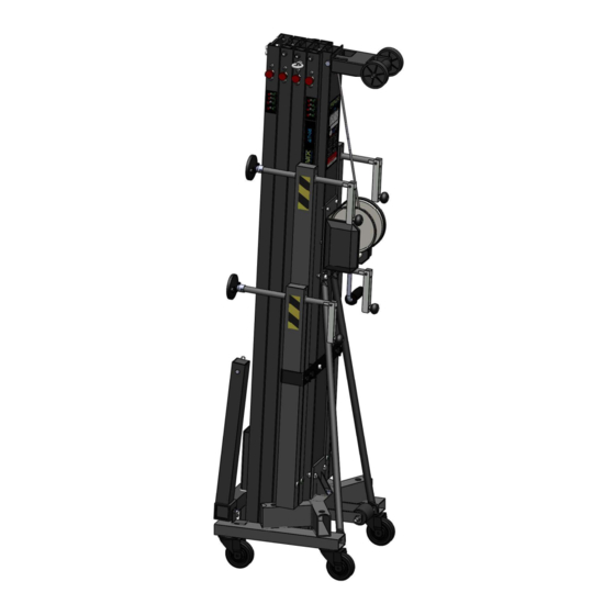
LEA ATENTAMENTE ESTE MANUAL Nivel de burbuja para ajustar posición verti- cal de la torre. Descripción del equipo: La torre elevadora AT-06B ha sido diseñada para levantar estructuras y aparatos de ilumi- nación y sonido en sentido vertical a diferen- tes alturas. -
Page 8: Normas De Seguridad
ESPAÑOL 3. NORMAS GENERALES DE SEGURIDAD - La torre elevadora es un elemento industrial diseñado para la elevación de cargas en sentido vertical, NUNCA se debe utilizar como plataforma elevadora de personas. - Colocar la torre elevadora sólo en superficies duras y planas, verificando que está en posi- ción vertical. -
Page 9: Instrucciones De Uso
ESPAÑOL 4. INSTRUCCIONES DE USO 7. Elevación: Para elevar los perfiles hay que 1. Colocar la torre elevadora sobre una su- seguir un orden concreto. El primer perfil perficie plana y firme en su emplazamiento que hay que subir siempre será el más aleja- de trabajo. -
Page 10: Mantenimiento
ESPAÑOL 5. MANTENIMIENTO 9. En caso de que la torre elevadora se que- de bloqueada en algún proceso del descenso, 1. Comprobar periódicamente el estado del hay dos opciones para intentar liberarla. La cable. Si un cable presenta rotura de hilos o primera siempre será... -
Page 11: Riesgos Específicos
ESPAÑOL 6. RIESGOS ESPECÍFICOS 7. SISTEMAS DE PREVENCIÓN Fallo del sistema de freno Sobre fallo del sistema de freno Puede producirse por deficiencias en el siste- Disponer de cabestrante conforme a las nor- ma de frenado o por una mala instalación. Si mas mencionadas en la directiva de seguri- deja de funcionar puede provocar un riesgo dad BGV C1, especialmente DIN EN ISO... -
Page 12: Introduction
Leg anchorage with safety pins. Bubble level to adjust tower’s vertical posi- tion. Equipment description: Lifting tower AT-06B has been designed to vertically raise structures and lighting and sound equipment to different heights. Tested by skilled personnel having passed all the operating, maximum load and dimen- sion inspections. -
Page 13: General Safety Rules
ENGLISH 3. GENERAL SAFETY RULES - The lifting tower is an industrial element designed to raise loads vertically, it must NEVER be used as a platform elevator for people. - Only place the lifting tower on firm flat grounds checking it is in vertical position. Do not use wedges or any strange elements to balance the hoist. -
Page 14: How To Use
ENGLISH 4. HOW TO USE 1. Place the lifting tower over a firm and flat 7. Elevation: To lift the profiles, a specific or- surface on its working place. der must be followed. The first profile to be raised will always be the one located furthest 2. -
Page 15: Maintenance
(B) slightly counterclockwise. Imme- diately afterwards, move again the safety pin 3. Lifting tower AT-06B, must be checked by (A) to closed position (S), until the end of the an expert a minimum of once a year as per section. -
Page 16: Specific Risks
ENGLISH 6. SPECIFIC RISKS 7. PREVENTION SYSTEMS Braking system failure About braking system failure May occur due to braking system deficien- Equip with winch complying with regula- cies or bad installation. If it stops working tions metioned in the BGV C1 directive, spe- it could cause a serious risk due to the rai- cially DIN EN ISO 12100:2011-03 and DIN sed load being out of control and may injure... - Page 17 Figura 2 Carga máxima Distancia* 45cm Maximum load 20cm Distance* 20cm 250kg 45cm 195kg *Distancia del centro de la carga a la torre *Distance from the center of the load to the tower Figura 3...
- Page 23 LIFTING TOWERS NOTAS / NOTES...
- Page 24 FENIX Stage, S.L.U. FENIX Stage, S.L.U. Avda. de los Trabajadores, 24 Horno de Alcedo 46026 - Valencia (Spain) Tel.: +34 96 125 08 55 export@fenixstage.com www.fenixstage.com www.fenixstage.com...
Need help?
Do you have a question about the AT-06B and is the answer not in the manual?
Questions and answers