Table of Contents
Advertisement
Available languages
Available languages
Quick Links
LIFTING TOWERS
AT
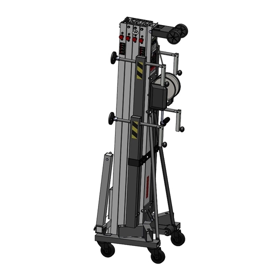
AT-05
Instrucciones
Instructions
Nº de serie:
Nº de serie:
Serial No.:
Fabricante:
Manufacturer:
FENIX Stage, S.L.U.
FENIX Stage, S.L.U.
Avda. de los Trabajadores, 24
Horno de Alcedo
46026 - Valencia (Spain)
Tel.: +34 96 125 08 55
export@fenixstage.com
www.fenixstage.com
www.fenixstage.com
-05
Advertisement
Table of Contents

Related Manuals for Fenix AT-05


Summary of Contents for Fenix AT-05
- Page 1 AT-05 Instrucciones Instructions Nº de serie: Nº de serie: Serial No.: Fabricante: Manufacturer: FENIX Stage, S.L.U. FENIX Stage, S.L.U. Avda. de los Trabajadores, 24 Horno de Alcedo 46026 - Valencia (Spain) Tel.: +34 96 125 08 55 export@fenixstage.com www.fenixstage.com www.fenixstage.com...
- Page 2 FENIX STAGE, S.L.U. Avda. de los Trabajadores, 24 Horno de Alcedo 46026 - Valencia (Spain)
- Page 3 DECLARATION OF CONFORMITY FENIX STAGE S.L.U. Adress: Avda. de los Trabajadores, 24 - Horno de Alcedo - 46026 - Valencia (Spain) Phone/fax: +34 96 125 08 55 / +34 96 125 13 05 VAT No.: ESB-91423046 We declare at our exclusive liability the conformity of the product:...
- Page 4 Verificación UVV / UVV Checking Verificación fábrica / Factory verification verificado en: Firma / Signature Fecha / Date Verificador / Verifier verified on: [BGV C1, BGG 912] Partes comprobadas / Tested parts Conclusiones / Conclusions Primera verificación experto / First expert verification Firma / Signature Fecha / Date Verificador / Verifier...
- Page 5 / unfolding of the entire profile sys- de perfiles. tem. Desde FENIX, con el fin de conseguir un From FENIX, in order to obtain an optimal funcionamiento óptimo de las torres eleva- performance and the longest lifetime of the...
-
Page 6: Table Of Contents
ÍNDICE 1.- INTRODUCCIÓN 2.- DATOS GENERALES 2.1.- Datos técnicos 2.2.- Normativa de aplicación 3.- NORMAS DE SEGURIDAD 4.- INSTRUCCIONES DE USO 5.- MANTENIMIENTO 6.- RIESGOS ESPECÍFICOS 7.- SISTEMAS DE PREVENCIÓN INDEX 1.- INTRODUCTION 2.- GENERAL DATA 2.1.- Technical data 2.2.- Applicable regulations 3.- GENERAL SAFETY RULES 4.- HOW TO USE 5.- MAINTENANCE... -
Page 7: Introducción
Anclaje de las patas por gatillos de seguridad. Nivel de burbuja para ajustar posición verti- cal de la torre. Descripción del equipo: La torre elevadora AT-05 ha sido diseñada para levantar estructuras y aparatos de ilu- minación y sonido en sentido vertical a di- ferentes alturas. -
Page 8: Normas De Seguridad
ESPAÑOL 3. NORMAS GENERALES DE SEGURIDAD - La torre elevadora es un elemento industrial diseñado para la elevación de cargas en sentido vertical, NUNCA se debe utilizar como plataforma elevadora de personas. - Colocar la torre elevadora sólo en superficies duras y planas, verificando que está en posi- ción vertical. -
Page 9: Instrucciones De Uso
ESPAÑOL 4. INSTRUCCIONES DE USO 1. Colocar la torre elevadora sobre una su- 7. Elevación: Para elevar los perfiles hay que perficie plana y firme en su emplazamiento seguir un orden concreto. El primer perfil de trabajo. que hay que subir siempre será el más aleja- do del cabestrante. -
Page 10: Mantenimiento
ESPAÑOL 5. MANTENIMIENTO 9. En caso de que la torre elevadora se que- de bloqueada en algún proceso del descenso, 1. Comprobar periódicamente el estado del hay dos opciones para intentar liberarla. La cable. Si un cable presenta rotura de hilos o primera siempre será... -
Page 11: Riesgos Específicos
ESPAÑOL 6. RIESGOS ESPECÍFICOS 7. SISTEMAS DE PREVENCIÓN Fallo del sistema de freno Sobre fallo del sistema de freno Puede producirse por deficiencias en el siste- Disponer de cabestrante conforme a las nor- ma de frenado o por una mala instalación. Si mas mencionadas en la directiva de seguri- deja de funcionar puede provocar un riesgo dad BGV C1, especialmente DIN EN ISO... -
Page 12: Introduction
Leg anchorage with safety pins. Bubble level to adjust tower’s vertical posi- tion. Equipment description: Lifting tower AT-05 has been designed to vertically raise structures and lighting and sound equipment to different heights. Tested by skilled personnel having passed all the operating, maximum load and dimen- sion inspections. -
Page 13: General Safety Rules
ENGLISH 3. GENERAL SAFETY RULES - The lifting tower is an industrial element designed to raise loads vertically, it must NEVER be used as a platform elevator for people. - Only place the lifting tower on firm flat grounds checking it is in vertical position. Do not use wedges or any strange elements to balance the hoist. -
Page 14: How To Use
ENGLISH 4. HOW TO USE 7. Elevation: To lift the profiles, a specific or- der must be followed. The first profile to be 1. Place the lifting tower over a firm and flat raised will always be the one located furthest surface on its working place. -
Page 15: Maintenance
ENGLISH 5. MAINTENANCE 9. In case the lifting tower gets blocked at any point during lowering process, there are two options to try to unlock it. The first will 1. Periodically check cable status. If the ca- always be to raise all profiles to its maximum ble seems to have broken wires or crushing, to try to untangle the cable and release the replace immediately with a new one. -
Page 16: Specific Risks
ENGLISH 6. SPECIFIC RISKS 7. PREVENTION SYSTEMS Braking system failure About braking system failure May occur due to braking system deficien- Equip with winch complying with regula- cies or bad installation. If it stops working tions metioned in the BGV C1 directive, spe- it could cause a serious risk due to the rai- cially DIN EN ISO 12100:2011-03 and DIN sed load being out of control and may injure... - Page 17 Figura 2 Carga máxima Distancia* 45cm Maximum load 20cm Distance* 20cm 250kg 45cm 195kg *Distancia del centro de la carga a la torre *Distance from the center of the load to the tower Figura 3...
- Page 23 LIFTING TOWERS NOTAS / NOTES...
- Page 24 FENIX Stage, S.L.U. FENIX Stage, S.L.U. Avda. de los Trabajadores, 24 Horno de Alcedo 46026 - Valencia (Spain) Tel.: +34 96 125 08 55 export@fenixstage.com www.fenixstage.com www.fenixstage.com...
Need help?
Do you have a question about the AT-05 and is the answer not in the manual?
Questions and answers