
Related Manuals for Warwick Pro Fet II


Summary of Contents for Warwick Pro Fet II
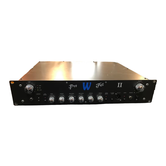
- Page 1 Warwick Service Manual Letzte Änderung Pro Fet II Last alteration 02.1999 Pro Fet II Front Pro Fet II Rear Subject to alteration HDB electronic Germany...
-
Page 2: Table Of Contents
Table of Contents Page 1.General 1. Technical Specifications 2. Measuring devices/methods 3. Safety Instructions 4. Components and spares 5. Accuracy of measurements 6. Dismantling instructions 2. Testing and regulating 1. Basic Configuration 2. Preamp 3. Power amp ⋅ Protections 6 f. ⋅... -
Page 3: General
General 1.1 Technical Specifications ⋅ Main supply............230 V / 115 V ⋅ Speaker Out............250 W / 4 Ohm ⋅ Input............... 25 mV ⋅ Frequency Filter BASS PUNCH ATTACK TREBLE LOW BOOST MID FREQ. MID LEVEL HIGH BOOST 30 Hz 75 Hz 230 Hz 250Hz... -
Page 4: Safety Instructions
General 1.3 Safety instructions Please read the safety instructions on the rear panel before opening the device. Above all, be sure to disconnect the device from the mains before commencing any repair work. Special care must be taken when working in the power amplifier areas as DC voltages in excess of >140V (power amplifier) may be present. -
Page 5: Testing And Regulating
Testing/Regulating 2.1 Basic Configuration To conduct a test on a Warwick Pro Fet II with the Gain \ Master measuring data given below, you must first set the Limiter \ Mute variable parameters in the channel strips to what Low Boost \ High Boost... - Page 6 (the Mute LED will illuminate and the relay will switch off). When the switch-off occurs, the voltage at T17 should be c. 0.6V . If the Pro Fet II has not switched off by the time the DC source voltage reaches 3V, there is a fault.
-
Page 7: Power Amp
72V(peak-to-peak) (Master: ). The output should then be connected with the 1ohm resistance. Directly afterwards, the Pro Fet II should switch to Standby mode and remain there until it is switched off. NOTE: If the load resistance can be varied to 2 ohms, the output stability can also be tested. - Page 8 Effects Return socket on the rear panel of the Pro Fet II . For the measurement to be carried out, it is essential that the signal be variable between 100Hz...1kHz...10kHz (switched is sufficient). A load resistance of 4 ohms (250W) and a voltage meter should be connected to the output.
- Page 9 Diagrams 3.1 Block diagram Page 9...
- Page 10 Diagrams 3.2 Wiring diagram Page 10...
- Page 11 Diagrams 3.3.1 Preamp Page 11...
-
Page 12: Effects
Diagrams 3.3.2 Effects PHONE PHONE EFF SEND EFFECT SEND EFF RET EFFECT RETURN rel1 LINE OUT LINE OUT rel2 TUNER OUT TUNER OUT +REL GROUND FREE 100n Chassis PCB Edge PCB Edge Page 12... - Page 13 Diagrams 3.3.3 Power amplifier Page 13...
-
Page 14: Board Layout's
Board Layout 4.1 FET2VV1 Page 14... - Page 15 Board Layout 4.2 FET2BU Page 15...
- Page 16 Board Layout 4.3 FET2PA Page 16...
-
Page 17: Oscillograms
Oscillograms 5.1 MP1-MP6 Page 17... -
Page 18: Analyser Curves
Analyser Curves 6.1 Frequency Filter Page 18...
Need help?
Do you have a question about the Pro Fet II and is the answer not in the manual?
Questions and answers