
Related Manuals for Forney PM IDD9000


Summary of Contents for Forney PM IDD9000
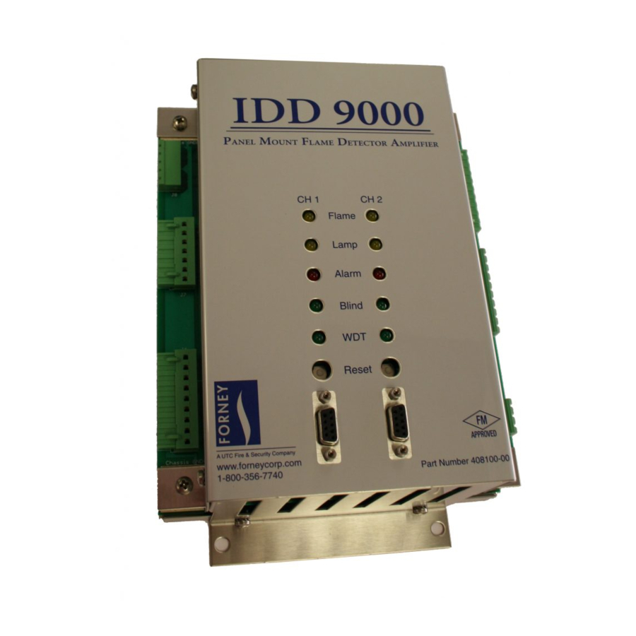
- Page 1 PM IDD9000 FLAME AMPLIFIER Part# 408100-00 Dual Channel Part# 408100-50 Single Channel Publication 372001-02 Rev L BURNERS IGNITERS DAMPERS CONTROLS www.forneycorp.com...
- Page 2 INTRODUCTION PROPRIETARY NOTICE SAFETY ICON DEFINITIONS DANGER WARNING CAUTION NOTICE 372001-02 Rev L...
- Page 3 REVISIONS REVISIONS DATE COMMENTS 02/2009 11/2010 06/2011 07/2011 10/2011 04/2014 01/2017 372001-02 Rev L...
- Page 4 TABLE CONTENTS 372001-02 Rev Kv...
- Page 5 TABLE OF CONTENTS Section 1 General Description Section 2 Installation 372001-02 Rev L...
- Page 6 TABLE OF CONTENTS Section 4 Maintenance Section 5 RMA/Warrant y Section 6 Spare Parts LIST OF FIGURES Figure 1-1 Figure 2-1 Figure 2-2 Figure 2-3 Figure 2-4 Figure 2-5 Figure 2-6 Figure 2-7 372001-02 Rev L...
- Page 7 TABLE OF CONTENTS LIST OF TABLES Table 1-1 Table 2-1 Table 2-2 Table 2-3 Table 2-4 Table 2-5 Table 2-6 Table 2-7 Table 2-8 Table 2-9 Table 2-10 Table 2-11 Table 2-12 Table 2-13 Table 3-1 Table 6-1 372001-02 Rev L...
-
Page 8: General Description
SECTION 1 GENERAL DESCRIPTION in connectors for ease of maintenance. Dual Channel Single Channel 372001-02 Rev L... - Page 9 output. This pulse train then serves as the input to the microprocessor. 372001-02 Rev L...
- Page 10 Figure 1-1 IDD 9000 Block Diagram 372001-02 Rev L...
-
Page 11: Specifications
SPECIFICATIONS Table 1-1 Part# 408100-00 Dual Channel Models: Part# 408100-50 Single Channel Environmental Extremes Power Requirements Operational Characteristics 3 relays are available for each channel (Lamp, Main Flame & Alarm*) 372001-02 Rev L... - Page 12 CERTIFICATIONS • FM Approved • CE Compliant Standards: immunity test immunity test EU Directives 372001-02 Rev L...
-
Page 13: Installation
SECTION 2 INSTALLATION CAUTION: WARNING: RECOMMENDED TEST/TUNING EQUIPMENT AND INSTRUCTIONS Table 2-1 Tuning Equipment Forney Part Description Manufacturer Number Forney Forney Forney 372001-02 Rev L... - Page 14 MOUNTING CONSIDERATIONS of this manual. ELECTRICAL CONNECTIONS CAUTION: Never connect or NOTICE: 372001-02 Rev L...
- Page 15 Figure 2-1 PM IDD 9000 External Connectors 372001-02 Rev L...
- Page 16 Table 2-2 PM IDD 9000 Pin-out Summary LABEL/SIGNAL NAME FUNCTION Neutral Neutral IDD Detector 372001-02 Rev L...
- Page 17 Label / Signal Function Name output IDD Detector Flame* Lamp* Alarm** Neutral 372001-02 Rev L...
- Page 18 2.3.1 AMPLIFIER UPGRADE WIRING TABLES Upgrading from an IDD-IIIA NOTICE: Table 2-3 IDD-IIIA to IDD 9000 PM-IDD 9000 Connector / Pin and Label Left Terminal Block 372001-02 Rev L...
- Page 19 PM-IDD 9000 Connector / Pin and Label Right Terminal Block *Note 1 *Note 1 *Note 1 Neutral *Note 2 372001-02 Rev L...
- Page 20 Upgrading from a PM DR6101E CAUTION: 372001-02 Rev L...
- Page 21 Table 2-4 PM DR6101E to IDD 9000 Channel 1 for UV-4 Applications PM DR-6101E IDD 9000 Connection / Pin and Label Left-side Right-side Neutral 372001-02 Rev L...
- Page 22 Table 2-5 PM DR6101E to PM IDD 9000 Channel 1 for IDD Applications PM DR-6101E IDD 9000 Connection / Pin and Label Left-side Right-side Neutral 372001-02 Rev L...
- Page 23 Table 2-6 PM-DR6101E to IDD 9000 Channel 2 for UV-4 Applications PM DR-6101E IDD 9000 Connection / Pin and Label Left-side Right-side Neutral 372001-02 Rev L...
- Page 24 Table 2-7 PM DR6101E to IDD 9000 Channel 2 for IDD Applications PM DR-6101E IDD 9000 Connection / Pin and Label Left-side Right-side Neutral 372001-02 Rev L...
- Page 25 2.3.2 GROUNDING THE PM IDD 9000 THE MOST IMPORTANT STEP NOTICE: 2.3.2.1 GROUNDING NEW APPLICATIONS RETROFITTING PM IDD 9000 WITH 2.3.2.2 IDD-II, IDD-IIU, OR UV4 DETECTORS RETROFITTING PM IDD 9000 WITH 2.3.2.3 AN IDD-ULTRA DETECTOR broken between the detector head and the boiler detector head casing must then be connected to the cable shield Figure 2-2 Grounding PM IDD 9000...
-
Page 26: Led Status Displays
This MUST LED STATUS DISPLAYS Table 2-8 PM IDD 9000 LED Indicators Indicator Function Flame Yellow Lamp Yellow Alarm Green Green normally. 372001-02 Rev L... - Page 27 FLAME DETECTOR CONNECTIONS NOTICE: Table 2-9 Control Inputs and Flame Detectors (bottom left side panel) Label / Signal Name Wire Color Flame Detector PIN Detector Green Black Detector Green Black 372001-02 Rev L...
- Page 28 Figure 2-3 Typical Installation with Sealtight Fitted 372001-02 Rev L...
- Page 29 2.5.1 CONNECTING IDD DETECTOR HEADS Figure 2-4 IDD Detector Head Wiring 372001-02 Rev L...
- Page 30 CONNECTING ONE IDD DETECTOR HEAD 2.5.2 TO BOTH IDD 9000 CHANNELS on each channel. Figure 2-5 Wiring one IDD Detector Head to both IDD 9000 Channels NOTICE: 372001-02 Rev L...
- Page 31 2.5.3 CONNECTING UV-4 DETECTOR HEAD Figure 2-6 UV-4 Detector Head Wiring NOTICE: 372001-02 Rev L...
- Page 32 2.5.4 CONNECTING AN IDD AND A UV-4 EITHER Figure 2-7 IDD and UV-4 Detector Head Wiring 372001-02 Rev L...
- Page 33 HARDWARE CONTROL INPUTS 2.6.1 BLIND INPUT - J8 NOTICE: 2.6.2 SENSE B INPUT - J8 372001-02 Rev L...
- Page 34 2.6.3 OPERATING PROFILE SELECT INPUTS - J7 NOTICE: ACTIVE PROFILE J7 pin 1 J7 pin 2 J7 pin 3 372001-02 Rev L...
-
Page 35: Operating Modes
OPERATING MODES NOTE: Mode 1: IDD PPS only Mode 2: UV-4 PPS only IDD GAIN CHECK DELAY 120 Seconds 372001-02 Rev L... -
Page 36: Pin Connector
CONFIGURING THE TERMIFLEX/ SMARTDISPLAY® TERMINAL WITH 25 PIN CONNECTOR NOTICE: lower left blue lower right 372001-02 Rev L... - Page 37 COM: DSP: KBD: COM: DSP: KBD: 372001-02 Rev L...
- Page 38 SECTION 3 AMPLIFIER TUNING Table 3-1 Keypad Commands Terminal Emulator Software Function Key strokes (TES) Button Question mark NOTE: 372001-02 Rev L...
- Page 39 MODE NOTICE: 3.1.1 IDD Channel Tuning 3.1.1.1 IDD Gain NOTICE: 372001-02 Rev L...
- Page 40 LEFT RIGHT Figure 3-1 Correct Gain Setting Figure 3-2 Incorrect Gain Setting >>>>>>>>>>>> >>>>>>>>>>>>««« Gain=0 Gain=1 NOTICE: 3.1.1.2 Frequency Ranges application requires this option. IDD Spectrum Ranges=2 372001-02 Rev L...
- Page 41 Freq Range(s): 1024 1024 CHG1 CHG2 NOTICE: screen. This is the Weight Factors Values 372001-02 Rev L...
- Page 42 Freq Range(s): Range 1 <956> Range 2 <956> 3.1.1.3 IDD Pick-Up and Dropout Points IDD SIGNAL: 956 DO: 300 IDD SIGNAL: 956 1100 DO: 500 NOTE: point. 372001-02 Rev L...
- Page 43 3.1.1.4 IDD Analog Output Low and High Points IDD ANALOG OUTS 1000 PU:800 LO: 0 DO:500 IDD ANALOG OUTS 1100 PU:800 DO:500 NOTE: 372001-02 Rev L...
- Page 44 3.1.2 UV-4 Channel Tuning Screen Values on Screen To Make Changes Notes the Multiplier Multiplier value accept the value. Dropout Points Dropout points accept the value. seen NOTE: point. most information to almost points. accept the value. low to a value lower than the CAUTION: critical processes.
- Page 45 Flame Failure Response Time Delay for Modes 1 and 2 FFRT = 3.8 Seconds CAUTION: Flame Failure: SELF-CHECK CYCLE TIME FOR MODES 1 AND 2 Self Check Delay = 120 Seconds 372001-02 Rev L...
-
Page 46: Saving Configuration
Regardless of the number of channels being used, both channels must be set to an equal Self-Check Cycle Time. If di erent self-check cycle times are set, the shorter of the two settings will be e ective on both Channels. Valid Range: 30 - 600 >... -
Page 47: Analog Outputs
FUNCTIONS UNAVAILABLE WHILE TUNING ANALOG OUTPUTS CAUTION: AMPLIFIER SHUTDOWN/FAILURE 372001-02 Rev L... -
Page 48: Maintenance
SECTION 4 MAINTENANCE This section contains maintenance instructions for the PM IDD 9000. CAUTION: WARNING: TUNING maintain optimum system performance. TROUBLESHOOTING 372001-02 Rev L... - Page 49 STORAGE AND HANDLING REQUIREMENTS 372001-02 Rev L...
- Page 50 SECTION 5 RMA/WARRANTY 372001-02 Rev L...
-
Page 51: Spare Parts
SECTION 6 SPARE PARTS Email Phone 372001-02 Rev L 372001-02 Rev L... -
Page 52: Recommended Spare Parts
RECOMMENDED SPARE PARTS Table 6-1 Replacement Parts Fuse Value Function Part No. 2.0A IDD Detector Power 62mA IDD Bias NOTE: 372001-02 Rev L... - Page 53 Commissioning Checklist Tuning Parameter Settings Sense Sense Sense Sense Sense Sense Sense Sense MODE 1 IDD GAIN FREQ RANGES CORNER 1 CORNER 2 CORNER 3 CORNER 4 WEIGHT 1 WEIGHT 2 IDD PICKUP- PPS IDD DROPOUT- PPS IDD ANALOG LOW- PPS IDD ANALOG HIGH- PPS MODE 2 UV-4 MULTIPLIER...
Need help?
Do you have a question about the PM IDD9000 and is the answer not in the manual?
Questions and answers