
Related Manuals for Forney PM IDD9000


Summary of Contents for Forney PM IDD9000
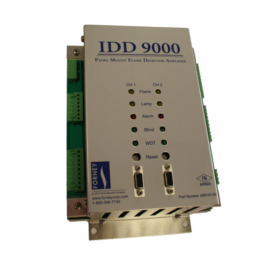
- Page 1 PM IDD9000 FLAME AMPLIFIER Part# 408100-00 Dual Channel Part# 408100-50 Single Channel Publication 372001-02 Rev L BURNERS IGNITERS DAMPERS CONTROLS www.forneycorp.com...
- Page 2 PROPRIETARY NOTICE The contents of this publication are proprietary data of Forney Corporation. Reproduction or use of any part of the publication for purposes other than the support of the equipment for which it is published is permissible only if expressly authorized in writing by Forney.
- Page 3 REVISIONS REVISIONS DATE COMMENTS 02/2009 Initial Release 11/2010 Updated details 06/2011 Correct Time-out references for tuning 07/2011 Add Table 2-13 10/2011 Remove Flame By-pass mode – Add TES 03/2012 Blind Input – J8 section 2.6.1, add single channel model, correct Alarm relay function &...
- Page 4 TABLE CONTENTS PM IDD9000 Flame Amplifier 372001-02 Rev Kv...
-
Page 5: Table Of Contents
TABLE OF CONTENTS Section 1 General Description 1.1 Specifications 1.2 Certifications Section 2 Installation 2.1 Recommended Test/Tuning Equipment and Instructions 2.2 Mounting Considerations 2.3 Electrical Connections 2.3.1 Amplifier Upgrade Wiring Tables 2.3.2 Grounding the PM IDD 9000 2.3.2.1 Grounding New Applications 2.3.2.2 Retrofitting PM IDD 9000 with IDD-II, IDD-IIU, or UV4 Detectors 2.3.2.3 Retrofitting PM IDD 9000 with an IDD-ULTRA Detector 2.4 LED Status Displays... - Page 6 TABLE OF CONTENTS Section 4 Maintenance 4.1 Tuning 4.2 Troubleshooting 4.3 Storage and Handling Requirements Section 5 RMA/Warranty Section 6 Spare Parts 6.1 Recommended Spare Parts LIST OF FIGURES Figure 1-1 IDD 9000 Block Diagram Figure 2-1 PM IDD 9000 External Connectors Figure 2-2 Grounding PM IDD 9000 Figure 2-3...
- Page 7 TABLE OF CONTENTS LIST OF TABLES Table 1-1 Table 2-1 Tuning Equipment Table 2-2 PM IDD 9000 Pin-out Summary Table 2-3 IDD-IIIA to IDD 9000 Table 2-4 PM DR6101E to IDD 9000 Channel 1 for UV-4 Applications Table 2-5 PM DR6101E to PM IDD 9000 Channel 1 for IDD Applications Table 2-6 PM-DR6101E to IDD 9000 Channel 2 for UV-4 Applications Table 2-7...
-
Page 8: Section 1 General Description
The amplifier provides power control, signal conversion, and processing control for Infrared Dynamic Detectors (IDD) series and UV-4 detectors. The IDD 9000 can support any of the following Forney flame detector head combinations: Dual Channel... - Page 9 A serial communication port for each channel is located on the front of the PM IDD 9000. These ports enable communication between the microprocessors on the board and a hand-held Termiflex/ SmartDisplay® via RS422/RS485 communication protocols. Forney also offers a Windows based software package, Terminal Emulator Software (TES), that supports diagnostics and tuning of the flame detection system.
-
Page 10: Figure 1-1 Idd 9000 Block Diagram
Upon completion of installation, the user must connect the Termiflex/SmartDisplay® to the amplifier and revise the tuning parameters suitable to detect the presence and absence of target flame. User-supplied tuning parameters are stored and remain unchanged until overwritten with new tuning parameters. Figure 1-1 IDD 9000 Block Diagram PM IDD 9000 Flame Amplifier 372001-02 Rev L... -
Page 11: Specifications
SPECIFICATIONS Table 1-1 Part# 408100-00 Dual Channel Models: Part# 408100-50 Single Channel Environmental Extremes Temperature: 0° to 60° C (32° to 140° F) Humidity: 5% to 95% non-condensing Power Requirements Supply: 120/240 Vac at 50/60 Hz Logic power: +12 Vdc Analog power: +15 Vdc Operational Characteristics... -
Page 12: Certifications
CERTIFICATIONS • FM Approved • CE Compliant Standards: FM 7610 -1997 Combustion Safeguards and Flame Sensing Systems Automatic burner control systems for burners and appliances burning EN 298 - 2012 gaseous or liquid fuels * Testing and measurement techniques - Electrostatic discharge EN61000-4-2 Ed. -
Page 13: Section 2 Installation
SECTION 2 INSTALLATION This section provides instructions and requirements for installing the Forney PM IDD 9000 assembly. CAUTION: This board contains “STATIC SENSITIVE” components. Use standard electrostatic-discharge (ESD) procedures whenever handling the PCB. WARNING: Ensure all Flame Detector amplifiers, detectors, and cables are installed properly, and the amplifier is programmed exactly as described in this manual. -
Page 14: Mounting Considerations
MOUNTING CONSIDERATIONS The PM IDD 9000 amplifier assembly should be installed in an equipment cabinet. If the amplifier is installed in a location where exposure to the elements is likely, a NEMA 4 cabinet should be used. The cabinet shall be located where the amplifier assembly is protected from direct exposure to water, dust and sunlight where the temperature/humidity remain within the ranges listed in the specification section of this manual. -
Page 15: Figure 2-1 Pm Idd 9000 External Connectors
Figure 2-1 PM IDD 9000 External Connectors PM IDD 9000 Flame Amplifier 372001-02 Rev L... -
Page 16: Table 2-2 Pm Idd 9000 Pin-Out Summary
Table 2-2 PM IDD 9000 Pin-out Summary LABEL/SIGNAL NAME FUNCTION J8 - Vac Opto Isolator Inputs Top of Left side panel (External connector Part # 9235311) AC Blind, 100 Vac –240 Vac AC Blind Neutral Neutral Return Shield Cable Shield / Chassis Ground AC Sense B, 100 Vac –240 Vac AC Sense B (PS0) - Page 17 Label / Signal Function Name J5 – Detector Analog Signal Outputs Top of Right side panel (External connector Part #9235312) 15 Vdc (fused) +15 Vdc UV-4 4-20mA 4-20 mA Return UV-4 Pulse Signal, 4-20mA return PPS 0-10 Vdc UV-4 Pulse Signal, 0-10V analog output Ground Electrical Ground return for detector UV-4 Detector...
-
Page 18: Amplifier Upgrade Wiring Tables
2.3.1 AMPLIFIER UPGRADE WIRING TABLES Upgrading from an IDD-IIIA The IDD-IIIA amplifier is a single channel amplifier that only supports and connects to a single IDD type flame detector. Only one channel of the PM IDD 9000 is needed to replace one IDD-IIIA amplifier. (If a dual channel PM IDD 9000 is used, the bottom board is Channel 1(CH1) and the top board is Channel 2 (CH2). - Page 19 IDD-IIIA Pin and Label on Amplifier Cover PM-IDD 9000 Connector / Pin and Label DET +50 Vdc (green wire) J4 Pin 3 IDD Detector 50 Vdc Bias Not Used DET. SIGNAL (White wire) J4 Pin 2 IDD Detector Signal METER (-) Right Terminal Block Not Used SENS B 115 Vac...
- Page 20 PM-DR6101E select the type of flame detector, and the Termiflex is used to select detector type for the PM IDD9000 channels. The bottom board of the PM IDD9000 is Channel 1 (CH 1) and the top board is Channel 2 (CH 2).
-
Page 21: Table 2-4 Pm Dr6101E To Idd 9000 Channel 1 For Uv-4 Applications
Table 2-4 PM DR6101E to IDD 9000 Channel 1 for UV-4 Applications PM DR-6101E IDD 9000 Pin and Label on Amplifier Cover Connection / Pin and Label Left-side P1-1 SHIELD J4, Pin 5 Shield P1-3 CH 1 SIG (White wire) J4, Pin 7 UV-4 Detector - Signal P1-4... -
Page 22: Table 2-5 Pm Dr6101E To Pm Idd 9000 Channel 1 For Idd Applications
Table 2-5 PM DR6101E to PM IDD 9000 Channel 1 for IDD Applications PM DR-6101E IDD 9000 Pin and Label on Amplifier Cover Connection / Pin and Label Left-side P1-1 SHIELD J4, Pin 5 Shield P1-3 CH 1 SIG (White wire) J4, Pin 2 IDD Detector - Signal P1-4... -
Page 23: Table 2-6 Pm-Dr6101E To Idd 9000 Channel 2 For Uv-4 Applications
Table 2-6 PM-DR6101E to IDD 9000 Channel 2 for UV-4 Applications PM DR-6101E IDD 9000 Pin and Label on Amplifier Cover Connection / Pin and Label Left-side P1-1 SHIELD J4, Pin 5 Shield P1-2 CH 1 SIG (White wire) J4, Pin 7 UV-4 Detector - Signal P1-4 POWER (15 Vdc) (Red wire) -
Page 24: Table 2-7 Pm Dr6101E To Idd 9000 Channel 2 For Idd Applications
CH 2/ 4-20mA OUT - L J5, Pin 7 IDD Detector - 4-20 mA Return * Unlike the PM DR6101E amplifier, ‘ALARM’ Relay on the PM-IDD 9000 amplifier is energized on ‘NO ALARM’ condition. PM IDD9000 Flame Amplifier 372001-02 Rev L... -
Page 25: Grounding The Pm Idd 9000
2.3.2 GROUNDING THE PM IDD 9000 Proper grounding assures proper operation and is in wiring the THE MOST IMPORTANT STEP IDD 9000 Amplifier. NOTICE: Improper grounding will cause check failures even when wiring and tuning is correct. 2.3.2.1 GROUNDING NEW APPLICATIONS New applications have the shield connected to the detector head in the cable connector which ensures proper grounding of the PM-IDD 9000. -
Page 26: Led Status Displays
*If the flame detector is directly installed on the sight pipe (without electrical insulating nipple), remove the shield connection to the ground on the amplifier end. Do NOT ground on both ends. The IDD 9000 has a Point of UNITY GROUND where all grounds converge. The hex standoff at the lower left corner of the IDD 9000 is the UNITY GROUND Point. -
Page 27: Flame Detector Connections
FLAME DETECTOR CONNECTIONS Connect the cable from the flame detector head to the J4 terminal along the left side of the amplifier chassis as indicated below in Table 2-9 and Figures 2-4 thru 2-7. NOTICE: Connecting/wiring a UV-4 detector head to the IDD detector terminals will damage the associated channel board. -
Page 28: Figure 2-3 Typical Installation With Sealtight Fitted
The detector cable must be in sealtight (or equivalent) conduit to avoid ingress of moisture or corrosive atmosphere to the connector. See Figure 2-3 for example. Figure 2-3 Typical Installation with Sealtight Fitted PM IDD 9000 Flame Amplifier 372001-02 Rev L... -
Page 29: Connecting Idd Detector Heads
2.5.1 CONNECTING IDD DETECTOR HEADS The IDD 9000 supports the IDD-II, IDD-IIL, IDD-IIU, IDD-J, IDD-UV, IDD-Ultra or an IDD-K. Wire each channel accordingly per IDD Detector Head as shown. Figure 2-4 IDD Detector Head Wiring PM IDD 9000 Flame Amplifier 372001-02 Rev L... -
Page 30: Connecting One Idd Detector Head To Both Idd 9000 Channels
CONNECTING ONE IDD DETECTOR HEAD 2.5.2 TO BOTH IDD 9000 CHANNELS One IDD Detector head can be wired as shown below to facilitate independent setting up a flame relay on each channel. Figure 2-5 Wiring one IDD Detector Head to both IDD 9000 Channels Diode Recommendation: 1N4002 to 1N4007. -
Page 31: Connecting Uv-4 Detector Head
2.5.3 CONNECTING UV-4 DETECTOR HEAD Wire each channel to a UV-4 on the IDD 9000 as shown. Figure 2-6 UV-4 Detector Head Wiring NOTICE: Connecting/wiring a UV-4 detector head to the IDD detector terminals will damage the associated channel board. PM IDD 9000 Flame Amplifier 372001-02 Rev L... -
Page 32: Connecting An Idd And A
2.5.4 CONNECTING AN IDD AND A UV-4 Either channel of the IDD 9000 can be wired for an IDD or UV-4 detector head. Wire according to the following diagram. Note: Each channel can only operate one detector at a time and should be wired to EITHER an IDD detector OR a UV-4 detector, not both on the same channel. -
Page 33: Hardware Control Inputs
The AC powered Sensitivity B, “Sense B”, operated input is provided for compatibility with installed wiring when retrofitting legacy Forney flame amplifiers. Powering the Sense B input is equivalent to grounding the “Profile Select 0” (PS0) input. The amplifier will operate with Profile number 0 if the Sense B input is not powered and Profile 1 when the Sense B input is powered. -
Page 34: Operating Profile Select Inputs - J7
2.6.3 OPERATING PROFILE SELECT INPUTS - J7 The IDD 9000 Flame Amplifier has non-volatile memory storage for eight sets of operating profiles, numbered from 0 to 7. The stored profiles are intended to allow for easy switching between commonly used burner operating conditions without requiring manual re-tuning of the flame amplifier. The active profile is selected by three 5-Volt logic level inputs, PS2, PS1, and PS0. -
Page 35: Operating Modes
OPERATING MODES NOTE: MODE 1: IDD PPS is for operating a single IDD series (flame flicker) type detector only. MODE 2: UV-4 PPS is for operating a single output pulse detector only. All operating profiles are initialized via a profile flag and with the default settings shown. Table 2-11 Operating Profiles Termiflex Display Mode 1: IDD PPS only... -
Page 36: Configuring The Termiflex/Smartdisplay® Terminal With 25 Pin Connector
SMARTDISPLAY® TERMINAL WITH 25 PIN CONNECTOR The PM IDD 9000 uses the same detachable Termiflex / SmartDisplay® unit for programming the amplifier as the previous Forney flame amplifiers, however the Termiflex / SmartDisplay® terminal with 25-pin must be reconfigured. NOTICE: If the Termiflex / SmartDisplay®... -
Page 37: Table 2-12 Termiflex/Smartdisplay® Configuration Settings For Idd 9000
Table 2-12 Termiflex/SmartDisplay® Configuration Settings for IDD 9000 Programming (Factory Default for Termiflex with 9-pin Adapter) COM: DSP: KBD: Baud: 19.2K Disp Ctl Chars: No Local Echo: No Parity: Even Disp Esc Chars: No Key Repeat: Slow Data, Stop Bits: 8,1 Cursor Visible: Yes Audible Keys: Yes DSP Serial Errs: Yes... -
Page 38: Section 3 Amplifier Tuning
The amplifier tuning mode can be reached using either the handheld Termiflex/SmartDisplay® or the Forney Terminal Emulator Software (TES) installed on a laptop computer. Table 3-1 Keypad Commands summarizes the keypad commands available in the IDD 9000 Flame Amplifier firmware program. Utilize the Commissioning Checklist at the end of this document to list tuning parameters used. -
Page 39: Mode
If MODE 1 is selected, a sequence of IDD channel tuning screens will follow. If available, use the USB oscilloscope to facilitate IDD tuning. Any oscilloscope with an FFT function may be used, but Forney recommends using the Forney Tuning Kit which includes an oscilloscope with FFT. Reference Forney Publication 372001-10 for more details. -
Page 40: Frequency Ranges
For best tuning and operation, adjust the gain up or down, so the most LEFT arrows are showing and no RIGHT arrows are visible. Use the F1, “DEC” and F2, “INC” keys on the Termiflex to make adjustments. The correct GAIN setting has the signal strength indicator “>” extending from the left side to the approximate center of the display while the burner is operating. - Page 41 The next tuning screen displays the lower and Freq Range(s): upper corner frequencies and weighting factors defined for the range. Press F1, “CHG” to make changes. 1024 1024 If two frequency ranges are selected, the CHG1 CHG2 display will show both frequency ranges’ corner frequencies and weighting factors.
-
Page 42: Idd Pick-Up And Dropout Points
Press F1 - CHG Freq Range(s): F1 - LO - type in lower corner frequency i.e. “100” F4 - OK F2 - HI - type in higher corner frequency i.e. “140” CHG1 F4 - OK F3 - WF - type in “2” F4 - OK F4 - OK Range 1... -
Page 43: Idd Analog Output Low And High Points
3.1.1.4 IDD Analog Output Low and High Points The analog output value corresponds to the average of the IDD ANALOG OUTS last five instantaneous counts of signal intensity. 1000 PU:800 LO: 0 DO:500 The IDD ANALOG OUTS screen shows the programmed values for the IDD analog output low and high points. -
Page 44: Uv-4 Channel Tuning
3.1.2 UV-4 Channel Tuning If operating Mode 2 is selected, the following screens will appear. Screen Values on Screen To Make Changes Notes UV-4 Count Multiplier Multiplier value goes from 1 Programmed Drop Press F1, “DEC” or to 5. It is a straight multiplier Out (DO) and Pick Up F2, “INC”... -
Page 45: Flame Failure Response Time Delay For Modes 1 And
Flame Failure Response Time Delay for Modes 1 and 2 The next screen shows: FFRT = 3.8 • FFRT setting being used. There are three choices Seconds available for the FFRT delay: 1.0, 2.0, 3.0, and 3.8 seconds. • Press F1, “CHG” and enter 1, 2, 3, or 4 (for 3.8) to change the setting. -
Page 46: Saving Configuration
Regardless of the number of channels being used, both channels must be set to an equal Self-Check Cycle Time. If different self-check cycle times are set, the shorter of the two settings will be effective on both Channels. During self-check the detectors are blinded for a brief interval. Valid Range: After a short delay, the signal levels are compared and 30 - 600... -
Page 47: Functions Unavailable While Tuning
FUNCTIONS UNAVAILABLE WHILE TUNING The following functions are not available when inside the tuning loop: • The self-check cycle timer is not incremented while inside the tuning loop. The timer resumes counting and the amplifier self-checks when the tuning loop is exited. •... -
Page 48: Section 4 Maintenance
(Refer to Table 6-1 for a list of fuses mounted on the PCB.) If any other component requires replacement, return the PCB to Forney for repair. 4. Use documentation supplied with the flame detector head to isolate a fault to the head or cable. -
Page 49: Storage And Handling Requirements
STORAGE AND HANDLING REQUIREMENTS Store the PM IDD 9000 amplifier in its shipping box until used. See the specifications section of this manual for storage temperature and humidity ranges. Normal static precautions should be taken in handling parts sensitive to electrostatic discharge (ESD). PM IDD 9000 Flame Amplifier 372001-02 Rev L... -
Page 50: Section 5 Rma/Warranty
SECTION 5 RMA/WARRANTY Forney Corporation warrants this product to be free of defective material and workmanship. Forney will replace this equipment as long as it is being used for its intended use and is found to be defective upon receipt up to the expiration of the warranty period. -
Page 51: Section 6 Spare Parts
SECTION 6 SPARE PARTS When ordering spare parts, contact Forney’s Aftermarket Department via any one of the following methods and furnish the following information. Email Phone spares@forneycorp.com 972-458-6100 or 972-458-6600 972-458-6142 or 1-800-356-7740 (24-hour direct line) 1. Contract number 2. Customer purchase order number 3. -
Page 52: Recommended Spare Parts
IDD 4-20mA Output 92357-04 62mA IDD Bias 2820-55 Insulating Pipe Nipple, Fiberglass 75168-01 Kit for IDD-Ultra Retrofit – 370279-01 Grounding NOTE: Drawing number, stock number, and part number are interchangeable for Forney supplied items. PM IDD 9000 Flame Amplifier 372001-02 Rev L... - Page 53 Commissioning Checklist Forney Contract No: ___________________________________________________________ Site: _____________________________________________________________________ Burner/Igniter No. _____________________________________________________________ Tuning Parameter Settings Profile #____ Profile #____ Profile #____ Profile #____ Sense Sense Sense Sense Sense Sense Sense Sense MODE 1 IDD GAIN FREQ RANGES CORNER 1 CORNER 2...
Need help?
Do you have a question about the PM IDD9000 and is the answer not in the manual?
Questions and answers