
Subscribe to Our Youtube Channel
Summary of Contents for paco SCG 0606
- Page 1 SOLAR CHARGE CONTROLLERS SCG 0606 / SCG 0808 / SCG 1010 / SCG 1515 Instruction Manual Please read user manual carefully before use.
-
Page 2: Overcharge Protection
Instructions and description of controllers with overcharge and over discharge protection, gasing regulation and temperature compensation. In photovoltaic solar systems lead batteries are often used for storing solar current. These batteries have to be protected against overcharging and over discharging. The Solar charge controller SCG0606 / SCG0808 / SCG1010 / SCG1515 fulfill both tasks in one device. - Page 3 4. Description 4.1 Functions The solar charge controller ● monitors the state of charge of the battery bank. ● controls the charging process. ● controls the connection/disconnection of loads. This optimizes battery use and significantly extends its service life. 4.2 Construction The solar charge controller consists of the following components: 1.
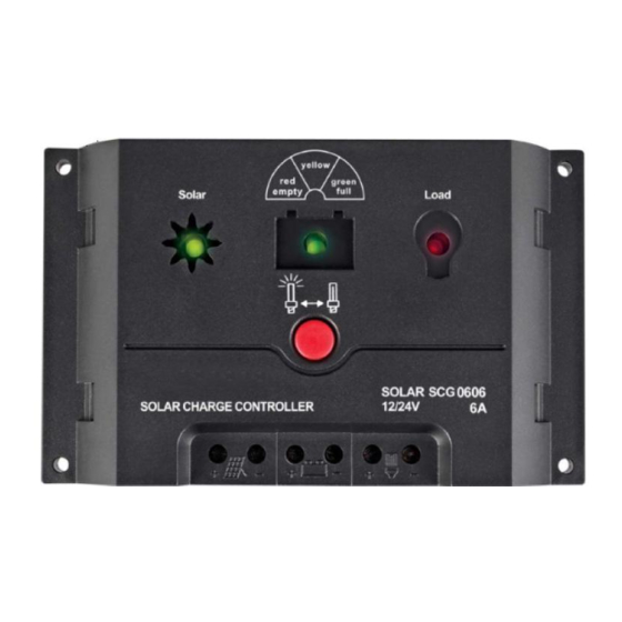
- Page 4 4.3 LED displays Battery LED Solar LED Load LED Normal mode Charging mode Load mode Solar reverse / short mode Load short / overload mode Solar over circuits mode Battery reverse mode Wrong battery type (RED) High mode temperature (RED) Note: : ILLUMINATE.
- Page 5 4.4 LED displays Meaning Status illuminates green battery charging by solar flashes green solar module polarity reverse or short circuit Solar LED extinguishes green over current protection deep-discharge deactivation, state of illuminates red charge<30% illuminates yellow battery weak, state of charge>40% to 70% illuminates green battery full, state of charge>80% to100% Battery LED...
-
Page 6: Advice For Installation
5. Advice for Installation The controller has to be installed possibly near the battery and must not be exposed to direct weather conditions. The controller is to be operated in well- ventilated rooms. The connection terminals have to point downwards when it is installed. - Page 7 1st step: Connect the battery Label the battery connection cables as a plus cable (A+) and a minus cable (A-). Lay the battery cables in parallel between the solar charge controller and the battery. Connect the battery connection cable with the correct polarity to the middle pair of terminals on the solar charge controller (with the battery symbol).
-
Page 8: Lightning Protection
7. Grounding The components in stand-alone systems do not have to be grounded - this is not standard practice or may be prohibited by national regulations. Consult the technical manual for more information. 8. Lightning protection In systems subjected to an increased risk of overvoltage damage, we recommend installing additional lightning protection / overvoltage protection to reduce dropouts. - Page 9 11. Attention 1.Avoid short circuits: danger of fire! 2.Users which may not switched off must be installed near the battery and protected by a fuse( e. g. position lights) 3.Sparking can develop especially in direct current systems during installation and operation. Do not install PV-components in rooms where easy flammable gases mixtures can develop (e.
-
Page 10: Technical Data
13. Technical data SCG 0606 SCG 0808 SCG 1010 SCG 1515 Solar charge controller / P/No. Max module input short circuit current at 25 C Max load output current at 25 C System voltage 12 V / 24 V Max. voltage of solar collector... - Page 11 CAUTION ALWAYS PLACE THE SOLAR CHARGE CONTROLLER IN AN ENVIRONMENT WHICH IS: A. WELL VENTILATED. B. NOT EXPOSED TO DIRECT SUNLIGHT OR HEAT SOURCE. C. OUT OF REACH FROM CHILDREN. D. AWAY FROM WATER / MOISTURE, OIL OR GREASE. E. AWAY FROM ANY FLAMMABLE SUBSTANCE. F.
Need help?
Do you have a question about the SCG 0606 and is the answer not in the manual?
Questions and answers