Table of Contents
Advertisement
Quick Links
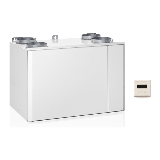
Ventilation unit with heat recovery
Planning, installation and operational instructions manual
This instruction covers all ventilation units with EDA-control.
EDA
Before installing and operating this unit,
please read this manual thoroughly, and retain it for further reference.
Enervent Digital Automation
www.enervent.fi
Advertisement
Table of Contents

Subscribe to Our Youtube Channel
Related Manuals for ensto enervent Plaza eco EDA

Summary of Contents for ensto enervent Plaza eco EDA
- Page 1 Ventilation unit with heat recovery Planning, installation and operational instructions manual This instruction covers all ventilation units with EDA-control. Before installing and operating this unit, please read this manual thoroughly, and retain it for further reference. Enervent Digital Automation www.enervent.fi...
-
Page 2: Table Of Contents
TABLE OF CONTENTS OVERVIEW WARNING TYPE MARKING TYPE DESCRIPTION FOREWORD OPERATING PRINCIPLE DUCT HEAT INSULATION INSTALLATION EQUIPMENT INSTALLATION DRAINING THE VENTILATION UNIT DEFINING ADDRESSES FOR OPERATING PANELS USER GUIDE STARTING THE UNIT SUPPLY AND EXTRACT AIR CALIBRATION OVERVIEW ON VENTILATION CONTROL PANEL AND CONTROL MAINTENANCE MAINTENANCE... -
Page 3: Warning
W/ V/ HZ / A: Enervent Pandion eco EDA Enervent Pelican eco EDA Enervent Pegasos eco EDA ENSTO ENERVENT OY Enervent Pegasos Cooler KIPINÄTIE 1 06150 PORVOO Enervent Pegasos eco XL EDA TEL +358 (0)207 528800 FAX +358 (0) 207 528844... -
Page 4: Type Description
TYPE DESCRIPTION Enervent LTR-3 eco EDE - CG Ventilation unit Choice of fan Control/possible Possible cooling mode frame (no markings after heating =alternative current fans) Ventilation unit with direct current fans. Ventilation unit with EDA control, without after heater. Ventilation unit with EDA control, with after heater. Ventilation unit with EDA control and water after heater. -
Page 5: Duct Heat Insulation
The ventilation engineer calculates the insulation requirements depending on the placement of the ducts and the air temperatu- res. When the insulation materials are designed, it must be taken into account that the extract air temperature may decrease significantly below zero degrees. The Optimizer software, which is available from Ensto Enervent’s website, can be used to calculate the extract air temperature with different outside air temperatures. Calculation software available from insulation material manufacturers can also be used when designing the insulation material thickness. -
Page 6: Equipment
EQUIPMENT INCLUDED IN THE DELIVERY OF THE UNIT: Enervent ventilation unit Control panel Control panel cable RJ4P4C, length 20 m (installation in a min 16 mm conduit) SEPARATELY SOLD EXTRA EQUIPMENT: Extra control panels max. 4/unit Control panel cable RJ4P4C, length 20 m Fine filter F7 inside the device Fine filter cassette F7 in duct casing Push button for over pressure function... - Page 7 Pandion on the floor, Pelican and Pegasos Install the unit on the floor or on a level built for the unit so that it stands on its own rubber pads. Leave at least a 10 mm opening between the back of the unit and the wall and at least a 15 mm opening to the sides. Also take into account the space needed for drainage below the unit.
-
Page 8: Draining The Ventilation Unit
DRAINING THE VENTILATION UNIT All Enervent-units with cooling must be drained. We recommend that also other units are drained. When air cools down (condenses) condense water forms i.e. in winter time when the humid inside air meets the cold heat recovery wheel or if the unit is equipped with cooling. -
Page 9: Defining Addresses For Operating Panels
DEFINING ADDRESSES FOR OPERATING PANELS Four (4) operating panels can be connected to an ventilation unit with EDA-control. If an unit is controlled with more than one panel, Modbus-addresses have to be defined for the panels in order for them to work in parallel. The address is defined with the short-circuit plugs delivered with the panel. -
Page 10: User Guide
USER GUIDE STARTING THE UNIT Before the unit is ready for use the following installations should take place: Assemble the unit as stated in the chapter Installation in this manual. Connect the drainage outlet with its own hose to an outflow supplied with a water lock (if the unit ventilates a space with swimming pool or if it is equipped with cooling). -
Page 11: Control Panel And Control
THE CONTROL SYSTEM AND OPERATING PANEL Fan speed settings Alarm Temperature settings 20°C Function symbol INFO row Status: Home Function Function Quick functions Menu selected selected with with right multifunction button left multifunction button Right multifunction Left multifunction button button Buttons for quick adjustment of temperature... - Page 12 DISPLAY Setting the fan speed Fan speed settings on direct current models (unit with direct current fans) Coloured bars on the display show which ventilation effect is active: 1 = 20 - 29 %, 2 = 30 - 39 %, 3 = 40 - 49 %, 4 = 50 - 59 %, 5 = 60 - 69 %, 6 = 70 - 79 %, 7 = 80 - 89 %, 8 = 90 - 100 %. The exact value is shown on the display, with an accuracy of one percent, for a short while when the buttons + and - for fan speed adjustment are pressed.
- Page 13 CONTROL OVERVIEW To get to the main menu of the control panel, press the right multi-choice button. In the menu, you navigate by using the up or down arrow. When you are in the menu the function alternatives, which are: ”Exit”; ”Reset”; ”Choose” and ”Change”, are shown on the bottom edge of the display.
- Page 14 MAIN MENU Main menu Alarm Measurements Time programs Info Settings Exit Choose ALARM Alarm 1-20/20 Alarm name space Alarm time DD:MM:YY HH:MM Alarm text Exit Reset All alarm and service messages are visible in the unit’s Alarm menu. 20 alarms are shown in the list. An alarm can have one of the following three statuses;...
- Page 15 List of alarms Alarm name Class Explanatory text row -- Alarm Delay NOTE! limit TE5 min AB or B After HRC +5°C 10 min Unit in failsafe mode. supply air cold TE10 min Supply air cold +10°C 10 min Unit in failsafe mode. TE10 max Fire risk supply temp high +55°C...
- Page 16 MEASUREMENTS Measurements Fresh air xx,x°C The Measurements menu is an informative menu where you can HRC sply xx,x°C read the different measurement results. Also measurements from Sply xx,x°C extra equipment like CO and RH% sensors can be read here. Exhst xx,x°C Explanations of the measurements: Exhst.
- Page 17 Time program events: Ventilation effect (1-8) for ventilation units with alternating current fans. The number of available ventilation effects depend on the fan effect’s initial settings. If the speed of the supply air and extract air fan is the same, the number of avai- lable effects are 8.
- Page 18 SETTINGS In this menu, you enter the settings needed for taking the unit into use. The code is 6143. Settings: Normal spd page 19 Fan speed page 19 page 19 Over pressure Temperatures page 20 Stove+CeVaCl+Overpr page 19 Boosting functions page 21 YYY (Standard duct pressure) page 23...
- Page 19 FAN SPEED Normal spd. Fan speed Supply fan Extract fan Normal spd. Ulkol. max: ##°C Over pressure Ulkol. min: ## °C Stove+CeVaCl+Overpr Back Change YYY (=Constant duct pressure) Exit Choose Over pressure The difference in speed between the supply air and extract air fan Supply fan is set in the normal speed menu.
- Page 20 TEMPERATURES Temp. settings Extract msrmnts: Displays the extract air or room temperature (depending on selected Exhst msrmnt ##,#°C temperature regulation) with one Sply msrmnt: ##,#°C decimal accuracy. Temp ctrl mde From Supply msrmnts: Displays the supply air temperature Setpoint: ##,#°C with one decimal accurancy.
- Page 21 BOOSTING FUNCTIONS Boosting functions Boosting settings: Selection of settings for boosting functions. Humidity: By activating humidity boosting allowed Boosting settings Carbon dioxide: By activating carbon dioxide boosting allowed □ Humidity Temp. boosting: By activating temperature boosting allowed □ Carbn dioxide □...
- Page 22 Humidity boosting: Function: Alternatives are Fixed limit and 48 h average humidity. Fixed limit works best during the heating-period, when the air is dry or is dried mechanically. If Fixed limit is used during the summer a situation can appear where the humidity outside can raise the humidity inside and turn on boosting.
- Page 23 SITUATION CONTROLS Situation controls Away Away Long away Fanspd Temp. drop ##°C □ Heat: □ Exit Choose Cooling: Back Change Fanspd: Selection of desired fan speed when the Away Long away function is active. Fanspd Temp. drop: Selection of desired temperature drop while Temp.
- Page 24 NIGHT COOLING Snight out li: Limit value for night cooling. Night cooling is al- lowed when the outside temperature exceeds the Night cooling set value. Snight out li ##,#°C Snight start: The night cooling function is activated when the Snight start ##,#°C extract air or room temperature is higher than Snight stop...
-
Page 25: Maintenance
MAINTENANCE The unit needs almost no maintenance. The maintenance is mostly limited to changing filters and cleaning the fans and rotor. During maintenance, cut the power from the main power switch or from the LTR-series unit by removing the service hatch. -
Page 26: Fault Alarms
FAULT ALARMS List of alarms Alarm name Class Explanatory text row -- Alarm Delay NOTE! limit TE5 min AB or B After HRC +5°C 10 min Unit in failsafe mode. supply air cold TE10 min Supply air cold +10°C 10 min Unit in failsafe mode. TE10 max Fire risk supply temp high +55°C... -
Page 27: Heat Exchanger Belt Replacement
HEAT EXCHANGER BELT REPLACEMENT There is a spare belt attached to all heat exchangers. In order to take use of the spare belt the heat exchager needs to be removed from the ventilation unit. Loosen the bayonet socket before removing the heat exchanger from the unit. Open the mainte- nance hatch (see below) and release the spare belt from the hold- ers. -
Page 28: Troubleshooting
TROUBLESHOOTING SUPPLY AIR COLD AFTER HEAT RECOVERY (TE05 min) Reason Action Belt of the heat exchanger is broken. Replace the belt. Belt greasy, causing slippage. Contact a service representative. * The extract fan has stopped. Contact a service representative. * The extract air filter is blocked. - Page 29 FREEZE RISK OF WATER COOLER (E45 min) Reason Action The circulation water pump has stopped. Activate the pump. If the problem persists, contact a service representative. Belt of the heat exchanger is broken. Replace the belt. Adjustor of water cooler’s valve defective. Contact a service representative.
-
Page 30: Technical Information
TECHNICAL INFORMATION... -
Page 31: Dimension Drawings
DIMENSION DRAWINGS Enervent EDA MD EN 2013_1... - Page 33 Enervent EDA MD EN 2013_1...
- Page 35 Enervent EDA MD EN 2013_1...
- Page 37 Enervent EDA MD EN 2013_1...
- Page 39 Enervent EDA MD EN 2013_1...
-
Page 41: Heat Recovery Efficiency
HEAT RECOVERY EFFICIENCY Enervent EDA MD EN 2013_1... - Page 43 Enervent EDA MD EN 2013_1...
-
Page 44: Characteristic Curves
CHARACTERISTIC CURVES... - Page 45 Enervent EDA MD EN 2013_1...
- Page 47 Enervent EDA MD EN 2013_1...
- Page 49 Enervent EDA MD EN 2013_1...
- Page 51 Enervent EDA MD EN 2013_1...
-
Page 52: Control Charts And Wiring Diagrams
CONTROL CHARTS AND WIRING DIAGRAMS This table shows whitch charts apply to each unit model. The numbers refer to the chart number. Additional Ventilation unit Chart number instuction principle chart All EDX-models Pingvin / LTR-2 eco EDE / LTR-3 eco EDE Pingvin / LTR-3 eco EDE-CG (CW) CG/CW Pingvin / LTR-3 eco EDW... -
Page 53: Water Coil Principle Charts
WATER COIL PRINCIPLE CHARTS Enervent EDA MD EN 2013_1... -
Page 54: Control Charts
CONTROL CHARTS 2. CONTROL CHART eco EDE... - Page 55 2a. CONTROL CHART EDE Cooler Enervent EDA MD EN 2013_1...
- Page 56 4. CONTROL CHART eco EDW...
- Page 57 4a. CONTROL CHART EDW Cooler Enervent EDA MD EN 2013_1...
-
Page 58: Wiring Diagrams
WIRING DIAGRAMS 6. WIRING DIAGRAM eco ED, eco EDE, ecoEDW OP. PANEL OP. PANEL... - Page 59 6a. WIRING DIAGRAM eco EDE Cooler OP PANEL OP PANEL Enervent EDA MD EN 2013_1...
- Page 60 6b. WIRING DIAGRAM eco EDW Cooler OP PANEL OP PANEL...
- Page 61 7. WIRING DIAGRAM UNIT INTERNAL CONNECTIONS Enervent EDA MD EN 2013_1...
- Page 62 8. WIRING DIAGRAM INTERNAL CONNECTIONS eco EDE models (electr. heating ≤ 2 kW)
- Page 63 9. WIRING DIAGRAM INTERNAL CONNECTIONS 3~ eco EDE models (electr. heating > 2 kW) Enervent EDA MD EN 2013_1...
- Page 64 11. WIRING DIAGRAM INTERNAL CONNECTIONS Cooler unit...
- Page 65 10. WIRING DIAGRAM EXTERNAL CONENCTIONS Central Vaccum Cleaner Indication Cooking hood Indication Free (PDS, EDE > 2kW) Overpressure Pushbutton (Accessory) NOT IN USE Manual Boost Pushbutton (Accessory) Overtime Pushbutton (Only In O ce Mode) (Accessory) External Alarm (Fire Hazard) Emergency Stop Enervent EDA MD EN 2013_1...
- Page 66 WIRING DIAGRAM EXTERNAL CONNECTIONS Indication of cooker hood and central vacuum cleaner...
-
Page 67: Outer Wiring
OUTER WIRING Location Explanation Delivery Current Example of cable type OP panel 1 Control panel 1 in every stan- RS-485 / Modbus RTU 20 m RJ11 4P4C cable included in dard delivery standard delivery OP panel 2 Control panel Extra equipment, RS-485 / Modbus RTU 20 m RJ114P4C cable included in max 2 st can be... -
Page 68: Air Flow Regulation Of Unit With Eda Control
AIR FLOW REGULATION OF UNIT WITH EDA CONTROL How to perform air flow regulation on a unit with EDA control : Determine which air amount and duct pressure values have been defined for the taget by the ventilation planner. Pre-install the vents according to the installation instruction. The characteristic curves for each unit is found in this operating manual. -
Page 69: Declaration Of Conformity
We declare that our products follows the provisions of low voltage directive (LVD) 2006/95/EEC, electromagnetic compa- tibility directive (EMC) 2004/108/EEC, machine directive (MD) 2006/42/EEC and ROHS II directive 2011/65/EEC. Manufacturer: Ensto Enervent Oy Manufacturer’s contact: Kipinätie 1, 06150 PORVOO FINLAND phone +358 (0)207 528 800, fax +358 (0)207 528 844 enervent@ensto.com, www.enervent.fi... -
Page 73: The Parameters Of Eda Control
THE PARAMETERS OF EDA CONTROL MENU SUB MENU PARAMETER FACTORY NOTE FIELD SETTING SETTING Settings 4x51 Fan speed Normal spd Supply fan 3 (30) 4x52 Extract fan 3 (30) 4x641 Ulkol.max -10,0°C Only PRO series units 4x642 Ulkol.min -0,1°C Only PRO series units 4x54 Over pressure Supply fan... - Page 74 4x75 RH DZ 4x72 Reset t 2 min 4x76 CO2 boost CO2 limit 1000 ppm 4x77 Max ventltn 8 (100) 4x78 CO2 P-band 200 ppm 4x80 CO2 I-time 1 min 4x81 CO2 DZ 50 ppm 4x79 Reset t 1 min 4x82 Temp.
Need help?
Do you have a question about the enervent Plaza eco EDA and is the answer not in the manual?
Questions and answers