Table of Contents
Advertisement
Quick Links
BENNETT 515-XP PUMP CONTROLLER
Installation & Service Manual
141938 Rev B 9/8/2021
Only Trained Personnel May Work on This Equipment
READ THIS MANUAL
This manual has important information for safe installation and operation of this equipment. Read and understand this manual before
applying power. Keep this manual and tell all service personnel to read this manual. If you do not follow the instructions, you can cause
bodily injury, death, or damage to the equipment.
Bennett 1218 E. Pontaluna Road, Spring Lake, MI 49456
USA 800-235-7618 ~ Outside USA 231-798-1310
sales@bennettpump.com ~ www.bennettpump.com
Advertisement
Table of Contents
Troubleshooting

Related Manuals for Bennett 515-XP

Summary of Contents for Bennett 515-XP
- Page 1 Keep this manual and tell all service personnel to read this manual. If you do not follow the instructions, you can cause bodily injury, death, or damage to the equipment. Bennett 1218 E. Pontaluna Road, Spring Lake, MI 49456 USA 800-235-7618 ~ Outside USA 231-798-1310...
- Page 2 For new manuals, visit our web page at IMPORTANT Examine the shipment immediately upon arrival to make certain there has been no damage or loss in transit. Bennett Pump Company, as shipper, is not liable for the hazards of transportation. Please make damage claims directly to the truck line.
-
Page 3: Table Of Contents
Bennett 515-XP Pump Controller Instruction & Service Manual Table of Contents TABLE OF CONTENTS TABLE OF CONTENTS SECTION 1: SAFETY INFORMATION General Information ........................................2 Hazardous locations ........................................2 Codes and Standards........................................2 Unauthorized Alteration of Bennett Products ..............................2 Abbreviations and Acronyms ..................................... - Page 4 Bennett 515-XP Pump Controller Instruction & Service Manual Table of Contents Page Intentionally Left Blank...
-
Page 5: Section 1: Safety Information
Bennett 515-XP Pump Controller Instruction & Service Manual Safety Information SECTION 1: SAFETY INFORMATION For safe installation of this equipment, read and understand all dangers, warnings, and cautionary information. Save this safety information in a readily accessible location. Look for the following warnings throughout the manual: Red and White “DANGER”... -
Page 6: General Information
American Petroleum Institute Recommended Practice RP 2003, Protection Against Ignitions Arising out of Static, Lightening, and Stray Currents. Service of the Bennett products and all accessories must be performed by a technician who is trained in accordance to all codes, standards, and regulations. -
Page 7: Section 2: Product Introduction
SECTION 2: PRODUCT INTRODUCTION The Bennett Model 515-XP Pump Controller is an interface device for third party point-of-sale systems. It allows the customer to use Bennett fuel dispensing equipment with any third party point-of-sale consoles that supports Bennett Remote Fuel Control Protocol and any third party POS systems that utilizes the Tokheim SCS or Veeder-Root ASR Protocols. -
Page 8: 515-Xp Pump Controller Assembly
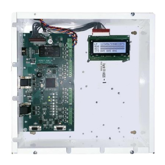
HARDWARE CONNECTIONS The 515-XP Pump Controller has four FUEL ONLY communication ports that are used to communicate to various third party point-of-sale providers. The communication (ports 1 through 4) are D connector panel mount, 9-pin female type. A male DB9 serial cable must be used to connect directly to the port using a straight through cable. - Page 9 Bennett 515-XP Pump Controller Instruction & Service Manual Product Introduction 515 PUMP CONTROLLER CIRCUIT BOARD ASSEMBLY DISPENSER COMMUNICATION DISPENSER COMMUNICATION DISPENSER COMMUNICATION DISPENSER COMMUNICATION LOOPS 13-16 LOOPS 9 – 12 LOOPS 1 – 4 LOOPS 5 – 8 POWER DISPLAY...
- Page 10 Power Supply (DC Power Input) J12 is a 2-position header used to connect the 24V Power Supply to the 515-XP Pump Controller. Each 515-XP Pump Controller uses one 120/240VAC, 60Hz circuit for power. Make sure the power source has the correct frequency and voltage.
- Page 11 Bennett 515-XP Pump Controller Instruction & Service Manual Product Introduction TS1, TS2, TS3, TS4 Shared Loop Dispenser Communication (1 to 32 Fueling Points) Terminal strips TS1, TS2, TS3, and TS4 are used for dispenser communications on a shared loop. This configuration allows the use of one pair of wires for fuel communication, with two fueling points daisy chained together.
- Page 12 DISPENSER & POS COMMUNICATION The 515-XP Circuit Board has several surface mount LEDs that are used for troubleshooting. Flashing LED’s indicate that the signals are present. For the communication ports, the controlling device must initiate communication before the 515 will respond. Note: If it is communicating with the console or dispenser, these LEDs are constantly blinking.
-
Page 13: Section 3: Installation Instructions
SECTION 3: INSTALLATION INSTRUCTIONS Bennett Pump Dispensers are to be installed by trained technicians. All technicians must be aware of ALL safety instructions. If you are not a Bennett trained technician, please contact Bennett Technical Support at 1-800-423-6638 for training information. -
Page 14: How To Remove Enclosure Cover
HOW TO MOUNT THE 515 PUMP CONTROLLER The 515-XP Pump Controller measures 12” x 12” x 4”. Each enclosure requires four mounting screws. These four screws are on 10 ½” by 10 ½” centers. Layout screws on wall 10 ½” x 10 ½” centers. -
Page 15: Ac Power Wiring
AC POWER WIRING The 515-XP Pump Controller is equipped with one 24V, 1.5A Power Supply Cable. Make sure the power source has the correct frequency and voltage (120V/240, 60 Hz) required for power. Note: The 515-XP Fuel Pump Controller must be connected to a dedicated receptacle. - Page 16 Bennett 515-XP Pump Controller Instruction & Service Manual Installation Instructions Fueling Point 1+2 Fueling Point 3+4 Fueling Point 5+6 Fueling Point 7+8 Fueling Point 9+10 Fueling Point 11+12 Fueling Point 13+14 Fueling Point 15+16 Fueling Point 17+18 Fueling Point 19+20...
-
Page 17: Station Interconnectin Diagram
Bennett 515-XP Pump Controller Instruction & Service Manual Installation Instructions STATION INTERCONNECTIN DIAGRAM... -
Page 18: Connect Point Of Sale Communication Wires
FLEET SYSTEM CO NFIGURATION (OPTIONAL) Fleet systems using the Bennett Remote Fuel Control Protocol through port 3 or 4 may need change prices set by the fleet system. A DIP Switch is used to control price changes from the fleet system. If the switch is on, the fleet system is not allowed to change any prices in the 515. - Page 19 Bennett 515-XP Pump Controller Instruction & Service Manual Installation Instructions POS Status View RFCP FP 12341234123412341 FP 00000000000000000 391 000 COUNTERS Dispenser Communication Status: 123456789ABCDEFG LOOPS LOOP NUMBER 1234123412341234 ADDRESS 0 FUELING POINT STATE CODE 0000000000000000 FUELING POINT STATE CODE...
- Page 20 Bennett 515-XP Pump Controller Instruction & Service Manual Installation Instructions Page Intentionally Left Blank...
-
Page 21: Section 4: Diagnostics & Troubleshooting
The Power up diagnostic messages can be viewed upon start-up of the 515 Pump Controller. Read the sections below for a complete description. OPENING DISPLAY MESSAGE The opening display message provides a summary of the 515 system as it relates to previous Bennett Pump products. Bennett Pump... - Page 22 515 or it can be “off-line”. An example of something that can cause the fueling point to be “off-Line” with the 515-XP box is if the fueling point is in the Managers Mode (programming mode) or in “Stand Alone”. In any case, you can see the different states the fueling point goes through during a sale by looking at the address for that fueling point in the 515-XP.
-
Page 23: Voltage Test Points
Bennett 515-XP Pump Controller Instruction & Service Manual Service Instructions VOLTAGE TEST POINTS WARNING: ELECTRONIC COMPONENTS ARE STATIC SENSITIVE. USE PROPER STATIC PRECAUTIONS (STATIC STRAPS) BEFORE WORKING ON THE EQUIPMENT WARNING: MAKE SURE THIS EQUIPMENT IS CORRECTLY GROUNDED. FAILURE TO DO SO CAN CAUSE INJURY OR DAMAGE THE EQUIPMENT. -
Page 24: Troubleshooting
To place an order for parts please contact us by mail, email, phone, fax, or web using the information provided below. Note: Verbal orders cannot be accepted. A signed purchase order must be faxed or emailed to the Bennett Order Entry Department at 231-799-6202 or customerservice@bennettpump.com. -
Page 25: Spare Parts List
Bennett 515-XP Pump Controller Instruction & Service Manual Service Instructions SPARE PARTS LIST The parts listed in the table below are basic components needed for a new or existing 515 Pump Controller may require basic and/or additional materials such as bolts, fittings, etc. These items can be found in your local hardware store. If not please feel free to contact our Bennett Customer Service Group at 1-800-719-6050. - Page 26 Bennett 515-XP Pump Controller Instruction & Service Manual Service Instructions Page Intentionally Left Blank...
-
Page 27: Appendix A: Manager's Mode
If the CANCEL key is pressed while in the Manager’s Mode, the Manager’s Mode is exited, and the display returns to the Idle Message Display. Programming the 515-XP Fuel Controller is done using a Manager’s Keypad that is shipped with each 515 unit. The keypad is normally disconnected and stored in the enclosure when not being used. -
Page 28: Mode 2 - Fueling Point Communication Down Counters
Bennett 515-XP Pump Controller Instruction & Service Manual Appendix A: Manager’s Mode MODE 2 – FUELING POINT COMMUNICATION DOWN COUNTERS Mode 02 shows the number of times each fueling point leaves the down state. The first display shows the counters for fueling points 1 through 8, and the second display shows the counters for fueling points 9 through 16. -
Page 29: Mode 5 - Fueling Point Communication Performance Counters
Bennett 515-XP Pump Controller Instruction & Service Manual Appendix A: Manager’s Mode MODE 5 – FUELING POINT COMMUNICATION PERFORMANCE COUNTERS Mode 5 shows the communication performance counters for each fueling point. The display shows three communication numbers for each fueling point and each display line provides the data for a single dispenser. Therefore, eight displays are required to provide the data for 32 fueling points. -
Page 30: Mode 11 - De-Authorization Failure Counters
Bennett 515-XP Pump Controller Instruction & Service Manual Appendix A: Manager’s Mode Note: The Counter ID is the Loop Number and Dispenser Address Type (0 or 1). The dispenser address type (0 or 1) is set in the Dispensers Operators Manual-Mode 22. Use the table below to identify the Counter ID and Fueling Point. -
Page 31: Mode 48 - Restarting The Software
Bennett 515-XP Pump Controller Instruction & Service Manual Appendix A: Manager’s Mode Note: The Counter ID is the Loop Number and Dispenser Address Type (0 or 1). The dispenser address type (0 or 1) is set in the Dispensers Operators Manual-Mode 22. Use the table below to identify the Counter ID and Fueling Point. - Page 32 Bennett 515-XP Pump Controller Instruction & Service Manual Appendix A: Manager’s Mode Page Intentionally Left Blank...
-
Page 33: Appendix B: Dispenser Configuration For 4-Wire & 2-Wire Installations
WIRE INSTALLATIONS Use the table below as a guide for configuring 2-wire (new) and 4-wire (retrofitted) 515-XP box installations. Refer to your dispenser’s operator’s manual for programming information. If a problem occurs or troubleshooting help is needed, please contact Bennett Technical Support at 1-800-423-6638. - Page 34 Bennett 515-XP Pump Controller Instruction & Service Manual Appendix B: Dispenser Configuration Page Intentionally Left Blank...
-
Page 35: Bennett Limited Warranty
Bennett specifications for a period of ninety (90) days from the date of original invoice. Bennett shall use its best effort to correct such defects and to supply to purchaser at Bennett’s expense, a corrected version within a reasonable time after purchaser notifies Bennett in writing of any defects and provides the programs and instructions required to reproduce the claimed defect. - Page 36 Bennett 1218 E. Pontaluna Road, Spring Lake, MI 49456 USA 800-235-7618 ~ Outside USA 231-798-1310 sales@bennettpump.com ~ www.bennettpump.com...
Need help?
Do you have a question about the 515-XP and is the answer not in the manual?
Questions and answers