Table of Contents
Advertisement
Advertisement
Table of Contents

Related Manuals for Ecolab Advanced Laundry

Summary of Contents for Ecolab Advanced Laundry
- Page 1 Advanced Laundry Control System Installation & Operation Manual Retain this manual for installation, operation, programming, and servicing information. 37179/0404/0707 Copyright Ecolab Inc. 2007 9258-2021 Advanced Laundry Control System Installation & Operation Manual...
- Page 2 This page intentionally left blank. Advanced Laundry Control System Installation & Operation Manual...
-
Page 3: Table Of Contents
Program Mode Navigation............... 21 QUICKSTART – See Figure 4 – 2 ..............23 ACCT SETUP – See Figure 4 – 3 ..............25 WASHER SETUP – See Figure 4 – 4 ............27 Advanced Laundry Control System Installation & Operation Manual... - Page 4 Periodic Cleaning ................... 49 10.2 Pump Tube Replacement ................49 10.3 Tube Lubrication..................... 49 10.4 Service......................50 10.4.1 Pump Module Disassembly ..............50 10.4.2 Pump Module Disassembly ..............50 10.4.3 Power Wiring ................... 51 Advanced Laundry Control System Installation & Operation Manual...
-
Page 5: System Introduction
This manual has been written and illustrated to present the basic installation, operation and servicing instructions of the Advanced Laundry Control System. This manual applies to current units. Future versions may have additional features; check unit packing for the latest revision. -
Page 6: System Features
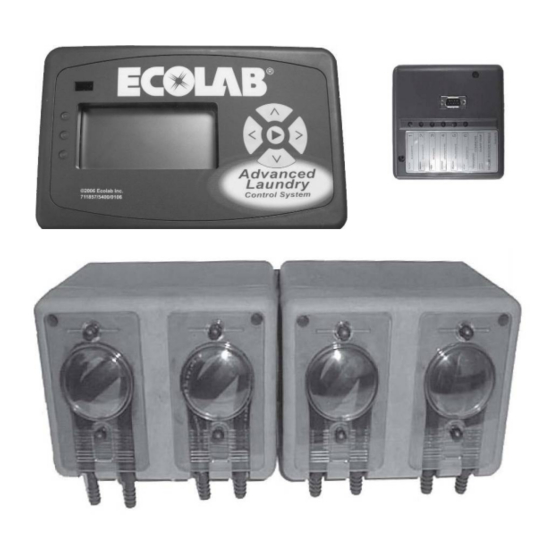
Control System “Controller” is connected to the “Machine Interface”. The Machine Interface communicates a “supply signal” from the laundry machine to the Controller. Once a signal is received, the Advanced Laundry Control System will pump products based on how you have programmed it. - Page 7 Figure 1-1 Washer Controller Supply Signals Advanced Laundry Control System Installation & Operation Manual...
- Page 8 Right Side View Bottom View Advanced Laundry Control System Installation & Operation Manual...
-
Page 9: Controller Description
Gnet connector: For future use. System expansion port: For future use. “Machine Interface” (DB-9 female) connector: This provides the communication link between e Controller and the Machine Interface. Attach the 10' cable here. Advanced Laundry Control System Installation & Operation Manual... -
Page 10: Specifications
2.0 Specifications Pump Module Assembly Controller Advanced Laundry Control System Installation & Operation Manual... -
Page 11: Machine Interface
The 10' (3.05 meter) cable is intended for the Machine Interface to Controller connection. • The 20' (6.10 meter) cable is intended for the Pump Module to Controller connection. • An optional 50' (15.24 meter) cable is also available. Advanced Laundry Control System Installation & Operation Manual... -
Page 12: General And Environmental Specifications
Product pickup and output supply tubing, an d probes. • For long Controller to Pump Module distan ces, a 50' (15.24 meter) cable may be ordered. • Optional Flush Manifold. • Optional controller swivel mount bracket. Advanced Laundry Control System Installation & Operation Manual... -
Page 13: Pump Module Installation
Cut the tie-wrap to remove the Flush Jumper Plug. Remove the Flush Jumper Plug from the flush connector on the underside of the Pump Module. IMPORTANT: Retain the Flush Jumper Plug for future use. Connect Flush Manifold cable to flush connector on the Pump Module. Advanced Laundry Control System Installation & Operation Manual... -
Page 14: Controller Installation
Use the optional mounting bracket for installation on horizontal surfaces. Attach the stainless steel mounting plate on the back of the controller with provided screws. Line up the holes of stand with the holes on the side of the plate. Advanced Laundry Control System Installation & Operation Manual... -
Page 15: Mounting To Machine Wall
Complete steps 2-5 in section 3.4.2 – Mounting on Horizontal Surfaces. Mount the “L” bracket using the four provided mounting screws. Attach the base of the optional mounting bracket to the “L” bracket using the two provided nut/bolt assemblies. Advanced Laundry Control System Installation & Operation Manual... -
Page 16: Machine Interface Installation
Electrical connections between the MI and signal wires must be made with screw terminals. Use the following color codes for both “Timer” and “Relay” modes – see section 4.1.1 for mode explanations: Advanced Laundry Control System Installation & Operation Manual... -
Page 17: Chart Stop Wiring
“events” or fills of the machine. Regular supply signals are not needed. Electrical connections between the was her and signal wires must be made with screw terminals. Event mode wiring connections below: Advanced Laundry Control System Installation & Operation Manual... -
Page 18: Micromode Signal Wiring
If you add product through top-mounted compartments use the delay feature of the Advanced Laundry Control System to allow the washer to fill before adding chemical. Use tie wraps or hose clamps to ensure that the tubes are secured at the washer entry point. -
Page 19: Programming
4.0 Programming General Information The information provided will take you step-by-step through the programming of the Advanced Laundry Control System Controller. Refer to figures 4-1 through 4-10 to help you access the various screens. 4.1.1 Definitions and Conventions • Menu – a selection of action choices presented on the single-line LCD display. -
Page 20: Pump Lockout
Post-flush time is programmable (5 to 999 seconds). • If water flow falls below 0.65 GPM during manifold operation, all pumps will stop and, after a two second delay, an alarm will activate. Advanced Laundry Control System Installation & Operation Manual... -
Page 21: Formula Load Counter
Program Mode menus are linked to display icons. • Program modes may be accessed incrementally, by pressing the NEXT key. • Press and hold keys to use the “auto key repeat” feature for faster scrolling. Advanced Laundry Control System Installation & Operation Manual... - Page 22 Figure 4-1 Enter Password ► ► < > Λ QUICKSTART ► ACCT SETUP ► WASHER SETUP ► FORMULA PROG ► ► RECORDS ► PRIME MODE ► TIME CALIB ► DIAGNOSTIC EXITING 5 Advanced Laundry Control System Installation & Operation Manual...
-
Page 23: Quickstart - See Figure 4 - 2
(see Section 4.9 for information on calibrating pumps). If you select NO and press the RIGHT arrow key, you will move to the WASHER ID screen. > TIME CALIB CALIB? > CALIB? WASHER ID 1 Advanced Laundry Control System Installation & Operation Manual... - Page 24 50LB (15 to 600 LBS dry linen) Λ > to scroll number of products PRODUCTS 4 ( 3, 4, 5, or 6 ) Λ to toggle CALIB? ( YES or NO ) Advanced Laundry Control System Installation & Operation Manual...
-
Page 25: Acct Setup - See Figure 4 - 3
The yellow LED will flash, indicating the change is occurring. The yellow LED will stop flashing when the default settings are complete. This takes approximately 90 seconds. If you select NO and press the RIGHT arrow key, you will move to the ACCT NUMBER screen. Advanced Laundry Control System Installation & Operation Manual... - Page 26 PRODUCTS 4 ( 3, 4, 5, or 6 ) Λ > to toggle PRIME DISABL ( Enable or Disable ) Λ > to toggle CALIB? N (YES or NO) Advanced Laundry Control System Installation & Operation Manual...
-
Page 27: Washer Setup - See Figure 4 - 4
FLSH – Use the UP/DOWN arrow keys to scroll add-on flush times (5 – 999 seconds available). The value is the time (in seconds) that the Flush Manifold will continue to flush after the pump stops running. Press the RIGHT arrow key to save displayed flush time. Advanced Laundry Control System Installation & Operation Manual... - Page 28 SIGNL 2 SEC ( 1, 2, 3, 5, 10, or 20 sec ) Λ ► to scroll add-on flush times FLSH 5 SEC ( 5 – 999 sec ) Advanced Laundry Control System Installation & Operation Manual...
-
Page 29: Formula Prog - See Figure 4 - 5
Use the UP/DOWN arrow keys to scroll Chart Stop delay times (00 – 99 MINUTES available). Press the RIGHT arrow key to save displayed Chart Stop delay for the noted formula/pump. Advanced Laundry Control System Installation & Operation Manual... - Page 30 (000.0 – 333.3) Λ to select pump delay for 01 P1 DLY 002 > Formula 1, Pump 1, Level (2 – 999 sec) NOTE: Figure 4–5 is continued on the next page. Advanced Laundry Control System Installation & Operation Manual...
- Page 31 REPEAT STEPS for formulas 2-16 02 P1 DLY 002 > (pumps 1-6, pump delays, volumes for 3 levels, and chart stop). Λ to toggle ► DEFAULT? N (YES and NO) Advanced Laundry Control System Installation & Operation Manual...
-
Page 32: Event Mode - See Figure 4 - 6
Use the LEFT arrow key to move back to the event selection area of the screen to select the next event to program. Use the RIGHT arrow key to move completely off the screen to save the Event Mode program and move to the next Washer Setup screen. Figure 4-6 Advanced Laundry Control System Installation & Operation Manual... -
Page 33: Records - See Figure 4 - 7
CLEAR CNT? – Use the UP/DOWN arrow keys to toggle between YES and NO. If you select YES, all load counts will be cleared. Press the RIGHT arrow key to accept the displayed response and advance to the next screen. Advanced Laundry Control System Installation & Operation Manual... - Page 34 Clear ALL run times for ALL pumps? CLEAR TIM? N > Λ to toggle (Yes or No) CLEAR LOAD COUNTS for ALL formulas? ► Λ CLEAR CNT? N to toggle (Yes or No) Advanced Laundry Control System Installation & Operation Manual...
-
Page 35: Prime Mode - See Figure 4 - 8
Press the RIGHT arrow key to advance to the next pump. Figure 4-8 > PRIME MODE PRIME PUMP 1? Λ > PRIME P1 to activate prime to deactivate prime PRIME PUMP 6? ► Λ PRIME P6 to activate prime to deactivate prime Advanced Laundry Control System Installation & Operation Manual... -
Page 36: Time Calib - See Figure 4 - 9
UP/DOWN arrow keys to toggle between YES and NO. If you select YES, all calibration volumes will be cleared. Press the RIGHT arrow key to accept the displayed response and advance to the next screen. Advanced Laundry Control System Installation & Operation Manual... - Page 37 (5 sec delay, 20 sec on) ENTER OUNCES Λ > ENTR OZ 003.3 to select volume dispensed (000.0 – 999.9 ounces) RESET ALL CALIBRATIONS TO FACTORY DEFAULT? ► CALDEFAULT N Λ to toggle (Yes or No) Advanced Laundry Control System Installation & Operation Manual...
-
Page 38: Diagnostic - See Figure 4 - 10
CHART STOP – this screen is used to confirm that the Chart Stop activates. Press the UP arrow key to activate Chart Stop and the DOWN arrow key to deactivate Chart Stop. Advanced Laundry Control System Installation & Operation Manual... - Page 39 ALARM audible alarm audible alarm Λ > to turn “ON” to turn “OFF” FLUSH FLUSH VALVE FLUSH VALVE Λ ► to turn “ON” to turn “OFF” CHART STOP CHART STOP CHART STOP Advanced Laundry Control System Installation & Operation Manual...
-
Page 40: Exit Program Mode
If there is no key activity, the controller will countdown for five seconds and the idle screen will be displayed. If you press the NEXT key prior to timing out, you will advance to the QUICKSTART menu. NO ACTIVITY ► EXITING Unit will exit programming QUICKSTART Advanced Laundry Control System Installation & Operation Manual... -
Page 41: Optional Equipment
– located on the Flush Manifold enclosure – will activate. This provides a safety interlock for no water pressure or other water flush system failures. Refer to the Flush Manifold Installation & Operation Manual for more information regarding the Flush Manifold option. Advanced Laundry Control System Installation & Operation Manual... -
Page 42: Account Features
16 formulas. The chemical flask icon indicates that a formu la number is displayed, nd the laundry cart icon indicates that the displayed number refers to load counts. > 01 WHT SHEET > 000000 < Advanced Laundry Control System Installation & Operation Manual... -
Page 43: Pumps Running
– see section 4.4 for information on enabling prime. From the idle screen, press the NEXT key twice to advance to the PRIME MODE screen. ► 01 WHT SHEET ► ENTER PASSWRD PRIME PUMPS > PRIME MODE See Section 4.8 for details Advanced Laundry Control System Installation & Operation Manual... -
Page 44: Set-Up And Operation
While viewing the pump and quantity on the screen, press both the NEXT key and the UP arrow key. The pump will run as if triggered by the machine and will dispense the programmed amount. Collect the output in a measuring cup to verify accuracy. Advanced Laundry Control System Installation & Operation Manual... -
Page 45: Troubleshooting
Machine Interface LEDs 4b. Troubleshoot washer for no during washer operation. If no LEDs, signals. verify presence of valid supply signal with voltmeter. 4c. If signals are good, replace the Machine Interface. Advanced Laundry Control System Installation & Operation Manual... - Page 46 Check that the Flush Manifold 2. Connect the Flush Manifold Interface cable is connected. Interface cable. Check if pump 3 washer signal Not counting formulas. Correct signal or programming received. error. Advanced Laundry Control System Installation & Operation Manual...
-
Page 47: Replacement Parts
9.0 Replacement Parts Pump Module Advanced Laundry Control System Installation & Operation Manual... -
Page 48: Controller
Controller Machine Interface Advanced Laundry Control System Installation & Operation Manual... -
Page 49: Optional Parts
Lightly lubricate new pump tubes with the following lubricants. Excessive and/or incorrect lubricants can cause premature pump tube failure. For Santoprene and EPDM pump tubes use Silicone lube For Silicone and Viton pump tubes use Vaseline type lube Advanced Laundry Control System Installation & Operation Manual... -
Page 50: Service
Pump motors are secured to the cabinet front by four phillips head screws. To add new motor (add a pump to an empty pump location), plug the motor wires into the appropriate locations in the Molex motor plug for that pump postion. Advanced Laundry Control System Installation & Operation Manual... -
Page 51: Power Wiring
The jumper configuration on the power terminal block determines the input voltage setting: 115 VAC: Jumper wire from terminal 1 to terminal 2; jumper wire from terminal 3 to terminal 4. 208 VAC: Jumper wire from terminal 2 t terminal 3. Advanced Laundry Control System Installation & Operation Manual...
Need help?
Do you have a question about the Advanced Laundry and is the answer not in the manual?
Questions and answers