
Related Manuals for Ecolab Apex2

Summary of Contents for Ecolab Apex2
- Page 1 Apex2 Installation and Operation Manual 370 Wabasha Street N. St. Paul, MN 55102 www.ecolab.com © 2012 Ecolab Inc. All rights reserved. 43569/5400/0112 Part No. 9223-2253...
-
Page 2: Table Of Contents
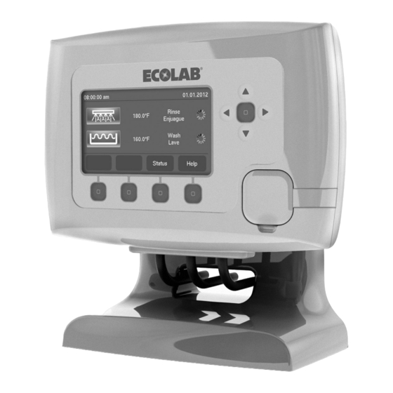
Rinse Additive Injection ................8 Plumbing Detergent Valve ................9 Optional Pressure Switch ................9 New Install Wiring ....................10 Machine Signals and Apex2 Power ............10-11 I/O Board Connections ................12 Sealing Block ....................13 Retrofit-Kit (Converting Apex to Apex2) ............14 Apex Rinse Additive Signal Wire ..............14 Apex 2 I/O Board ..................14... - Page 3 NOTICE means the possibility of equipment or property damage only. Principle of Apex2 The Apex2 System is a machine warewash control system that communicates actionable and intuitive information to the customer and creates an efficient interface for Ecolab sales representatives. This control system will help the customer achieve superior results with improved operational efficiency.
- Page 4 - “Pulse Feed” of detergent provides overshoot control when the wash tank concentration is near the desired set point. • A Timed Mode that is available for alternate detergent control when not using the probe. • A Detergent Manager that monitors probe control dispensing and automatically switches to a base lined feed condition when a dispensing error is detected.
- Page 5 Figure 2.1 12.005 10.772 9.235 14.699 Figure 2.2 Electrical Requirements The Apex2 Controller operates within the following: • Incoming Power • 100 to 240VAC , 50/60Hz • Detergent and Rinse Signal inputs • 24 to 240VAC , 50/60Hz, or 24VDC .
- Page 6 (P/N 9230-1022). Inputs (See Mechanical Installations for Wiring Diagram section 4) The Apex2 Controller operates with the following inputs (I/O Enclosure): • Inductive Probe (mandatory for operation in probe mode) • Rinse Thermistor (mandatory for all Apex2 Installations) •...
- Page 7 • Rinse Thermistor Apex2 Retrofit Kit (9223-1071) Contents: • Apex2 User Interface Module • Apex2 I/O Enclosure Cover & I/O Board assembly • Inductive Probe (12’) • RS-485 Communication Cable • Rinse Thermistor Apex2 New Customer Install Kit Dual Pump...
- Page 8 Mounting Controller 1. Choose an installation location that: • Allows visual display of the Apex2 Controller (see figure 4.1 below) • Permits shortest possible tube, wire, and conduit lengths. • Provides accessibility for adjustments and servicing. • Provides as much protection from moisture/steam and heat as possible.
- Page 9 Mount Apex2 I/O Enclosure Attach the Apex2 I/O mounting bracket to the wall using the supplied screws and plastic wall anchors. The installation should be secure, neat, and level. See Figure 4-4 Figure 4.4 Inductive Probe Installation For optimal equipment performance and reliability choose a location that is: •...
- Page 10 Rinse Thermistor/Injection Installation The rinse aid injection point must be installed downstream of the vacuum breaker, and a minimum of 6” (15.2 cm) vertically below the vacuum breaker. Note: Some international installations require this distance to be 30 cm (11.8”). The enclosure must be mounted so that the top of the rinse dispenser pump is below the injection point.
- Page 11 Detergent Valve 1. Connect 1/4” O.D. flexible copper tubing from the building water supply to the inlet side of the solenoid valve, located at the bottom of the Apex2 I/O enclosure. 2. Connect 1/4” O.D. flexible copper tubing from the outlet side of the solenoid valve to the Apex Detergent Dispenser.
- Page 12 If Apex2 must be connected to a source other than the dish machine for the main power, the electrical, overcurrent protection and grounding connections must comply with the applicable portions of the National Electric Code, ANSI/ NFPA 79 (latest edition), and/or other local electrical codes.
- Page 13 Note: For proper operation, both Detergent Signal and Rinse Signal (or pressure Note: For proper operation, both Detergent Signal and Rinse Signal (or pressure switch) switch) connections must be connected for all installations. connections must be connected for all installations. Main Power Main Power Connect Blue and Brown wires to constant voltage source.
-
Page 14: Inductive Probe
Apex2 I/O Board Connections Note: The components inside the Apex2 I/O enclosure are prewired Pass wires through the hole in the Apex2 I/O enclosure for the cable sealing block and connect to I/O Apex2 I/O board. Wires to pass through sealing block include: •... -
Page 15: Sealing Block
Wrap excess cable outside of the I/O enclosure to prevent electrical noise interference. After making wire connections, install the cable sealing block inside the Apex2 I/O Enclosure. 1. Place sealing block underneath wires and align the guides into position. - Page 16 Note: Disconnecting the white-to-yellow connection will cause the dispenser to function incorrectly and not fill reservoir. 3. Connect the supplied grey wire to the male connector of the white wire 4. Route the grey wire out the bottom of the rinse dispenser to the Apex2 I/O Enclosure Figure 4.14 Note: Leave the remaining white terminal connector unconnected.
- Page 17 I/O enclosure, causing the cover to unsnap from the stainless steel hinge pin. b. Do not throw the Apex board into the garbage! The board must be disposed of properly c. Ship to: Ecolab Hwy 251 & Rockton Rd. South Beloit, IL 61080 Figure 4.18 4.
-
Page 18: Apex 2 I/O Board
If necessary, use pliers to squeeze cover assembly onto hinge pin. NOTE: Avoid twisting the front cover as this may damage the Apex2 I/O board 2. Install Apex2 I/O Board Connections Refer to the I/O Board diagram, Figure 4.11 a. -
Page 19: Controller Setup
All setup parameters are accessed through the “Main Menu “of the Apex2 controller. The initial setup of the Apex2 controller is aided through the use of the Apex2 Setup Wizard that will be initiated upon initial startup of the controller. - Page 20 1. Set the duration of a muted alarm when the “Mute Alarm” button is pressed during an active alarm. Once the inputted time expires Figure 5.7 the screen Apex2 controller screen will revert from yellow back to red and the audible alarm will re-sound.
- Page 21 v. Alarm Priority...
- Page 22 • See trouble shooting table Can I wire a Rinse Max to an Apex2 IO Board? • No, different voltage requirements. Apex2 is DC and Rinse Max is AC How do I know if I have a faulty rinse pump motor? •...
-
Page 23: Alarms
If valve operates, verify correct wiring and presence of wash • signal 2. Detergent Dispenser Lid Switch Open; check lid position signal through Apex2 controller menu “Diagnostics & Troubleshooting- Dispenser Lid Position” If lid position is open, check wiring and lid switch on dispenser •... - Page 24 Note – Ensure the probe is in a location that will provide an accurate representation of the temperature of the wash tank. NOTE - Differences of up to +/- 5 °F (3°C) between the Apex2 controller reading and the dish machine guages are acceptable Apex2 Controller rinse 1.
- Page 25 1. Ethernet Communication Interrupted; check connectivity lights on Issue the Ethernet connection on the front of the Apex2 controller and on the connector on the Tablet PC. When Ethernet cord is connected and during data transmission, there should be a solid...
-
Page 26: Appendix
APPENDIX Performance Check Regular Inspection 1. Inspect the pump squeeze tube. If visibly worn or cracking, replace the squeeze tube even if it is working properly at the time. 2. Inspect all tubing connections for leaks, crack or loose fittings. Tighten or replace as necessary. -
Page 27: Replacement Parts Guide
Plastic Part Apex2 I/O Box Cover 9200-2119 Plastic Part Apex2 I/O Box Mounting Bracket 8526-0021 Plumbing 24V DC Solenoid Valve w/ Mounting Plate 9204-2051 Plumbing/Electrical 24V DC Solenoid (Only Coil) 8460-4321 Plumbing Blue Pump with 1 cc Squeeze Tube (Apex2 Standard) - Page 28 RS-485 Cable 50' 9259-2447 Electrical RS-485 Cable 6' 8374-0357 Electrical 24VDC Rinse Pump Motor Apex2 Dual Pump I/O Box Kit (Does not include 9223-1070 Installation Kit dispensers) Apex2 New Customer Install Kit (Single Pump, Does not 9223-1072 Installation Kit include Dispensers)
- Page 29 1/4" T x 1/4" MNPT Fitting for Pressure Reducing Valve 8563-4350 Plumbing Fitting Elbow 1/4" T x 1/4" MNPT Fitting for Solenoid Valve 9200-1034 Sensor Apex2 Rinse Aid Out-Of-Product Signal Wire for Retrofits 9230-2013 Sensor Inductive Probe 12' 9230-2014 Sensor...
- Page 30 Adjust Dispensing: Door Probe Adjust Dispensing Adjust Detergent Diagnostics & Troubleshooting Setup System Adjust Rinse Aid View Information Adjust Third Product Logout Adjust Detergent Set Point Adjust Detergent Adjust Rinse Aid Adjust Third Product Set detergent concentration: Range: 1-100, increments of 1 Default: 50 Titrate machine sump to determine concentration.
- Page 31 00:00:00 pm Adjust Dispensing: Door Timed Adjust Dispensing Adjust Detergent Diagnostics & Troubleshooting Setup System Adjust Rinse Aid View Information Adjust Third Product Logout Adjust Detergent Valve Run Time 2.5 Seconds Adjust Detergent Dose Interval Adjust Detergent Adjust Initial Detergent Charge Adjust Rinse Aid Adjust Third Product Set duration of detergent dispense per rack:...
- Page 32 Adjust Dispensing: Conveyor Probe Adjust Dispensing Adjust Detergent Diagnostics & Troubleshooting Setup System Adjust Rinse Aid View Information Adjust Third Product Logout Adjust Detergent Set Point Adjust Detergent Adjust Rinse Aid Adjust Third Product Set detergent concentration: Range: 1-100, increments of 1 Default: 50 Titrate machine sump to determine concentration.
- Page 33 Adjust Dispensing: Conveyor Timed Adjust Dispensing Adjust Detergent Diagnostics & Troubleshooting Setup System Adjust Rinse Aid View Information Adjust Third Product Logout Adjust Detergent Valve Run Time 2.5 Seconds Adjust Detergent Adjust Detergent Dose Interval Adjust Rinse Aid Adjust Initial Detergent Charge Adjust Third Product Set length of detergent dispense: Range: 1-30 seconds, interval of 0.1 seconds...
- Page 34 Adjust Dispensing: Flight Probe Adjust Dispensing Adjust Detergent Diagnostics & Troubleshooting Setup System Adjust Rinse Aid View Information Adjust Third Product Logout Adjust Detergent Setpoint Adjust Detergent Adjust Rinse Aid Adjust Third Product Set detergent concentration: Range: 1-100, increments of 1 Default: 50 Titrate machine sump to determine concentration.
- Page 35 Diagnostics & Troubleshooting Adjust Dispensing Diagnostics & Troubleshooting Probe Diagnostics Setup System Detergent Dispenser Lid Position View Information Machine Signal Interface Diagnostics Out of Product Alarms Dispensing Tests Logout Detergent Setpoint: 50 Probe Diagnostics Temperature Adjusted Probe Reading: 50 Raw Probe Reading: 50 Dispenser Lid Switch Position Total Dissolved Solids: 3500 Machine Signal Interface Diagnostics...
- Page 36 Setup System Adjust Dispensing Machine Setup Diagnostics & Troubleshooting Product Selection Setup System Language Set-Up View Information Alarms Date & Time Unit of Measurement Logout Reset to Default Settings Set Tablet Values Machine Setup Machine Mode: Conveyor Operating Mode: Probe Product Selection Language Set-Up Alarms...
- Page 37 Diagnostic Data Alarm Data Apex 2 I/O board: Serial number, build date and firmware version. Controller Board Information I/O Board Information 370 Wabasha Street N. St. Paul, MN 55102 www.ecolab.com © 2012 Ecolab Inc. All rights reserved. 43569/5400/0112 Part No. 9223-2253...
Need help?
Do you have a question about the Apex2 and is the answer not in the manual?
Questions and answers