Table of Contents
Advertisement
Quick Links
Feb.2002
SPECIFICATINS................................................................ 2
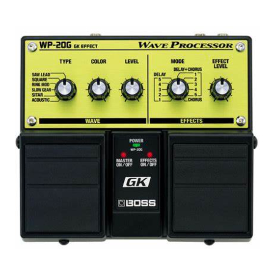
LOCATION OF CONTROLS .......................................... 4
LOCATION OF CONTROLS PARTS LIST ................... 5
EXPLODED VIEW ............................................................ 6
EXPLODED VIEW ............................................................ 8
EXPLODED VIEW PARTS LIST ..................................... 9
PARTS LIST...................................................................... 10
IDENTIFYING VERSION NUMBER ........................... 14
Copyright © 2002 ROLAND CORPORATION
All rights reserved. No part of this publication may be reproduced in any form without the written permission
of ROLAND CORPORATION.
TEST MODE..................................................................... 14
Block Diagram ................................................................. 18
Circuit Board (JACK BOARD) ...................................... 20
Circuit Board (JACK BOARD) ...................................... 21
Circuit Diagram (JACK BOARD) ................................. 22
Circuit Board (PANEL BOARD)................................... 24
Circuit Diagram (PANEL BOARD).............................. 25
17058016E0
SERVICE NOTES
Issued by RJA
Printed in Japan (0800) (AS)
WP-20G(T)
Advertisement
Table of Contents

Subscribe to Our Youtube Channel
Related Manuals for Roland WP-20G


Summary of Contents for Roland WP-20G
-
Page 1: Table Of Contents
PARTS LIST..............10 Circuit Diagram (PANEL BOARD)......25 IDENTIFYING VERSION NUMBER ......14 Copyright © 2002 ROLAND CORPORATION All rights reserved. No part of this publication may be reproduced in any form without the written permission of ROLAND CORPORATION. 17058016E0... -
Page 2: Specificatins
GK Connecting Cable: GKC-3 (3 m), GKC-5 (5 m), GKC-10 (10 m), C-13B(10 m) (Roland) Nominal Input Level GK Parallel Box: GKP-4 (Roland) 0 dBu = 0.775 Vrms GUITAR RETURN: -20 dBu In the interest of product improvement, the specifications and/or appearrance of this unit are subject to change without prior notice. - Page 3 WP-20G(T)
-
Page 4: Location Of Controls
Feb.2002 LOCATION OF CONTROLS fig.panel-h... -
Page 5: Location Of Controls Parts List
WP-20G(T) LOCATION OF CONTROLS PARTS LIST [Parts] Part Code Part Name Q’ty F344940301 ADAPTOR JACK DJ-0711B-020 G2017146 CASE G2017148 BOTTOM COVER G2357118 BOTTOM FOOT G2017621 BATTERY COVER G2537726 LABEL 13449155MF PHONE JACK (MONO) HTJ-064-12I G2217150 REAR PANEL 00564556 TCS5093-10-4152 F3159104... -
Page 6: Exploded View
Feb.2002 EXPLODED VIEW fig.panel-h... - Page 7 WP-20G(T) RIGHT SIDE LEFT SIDE...
- Page 8 Feb.2002 EXPLODED VIEW fig.panel-h...
-
Page 9: Exploded View Parts List
WP-20G(T) EXPLODED VIEW PARTS LIST [Parts] Part Code Part Name Q’ty G2017146 CASE G2357111 CUSHION R H5029851 PEDAL SHAFT 2215770201 PEDAL GUIDE BUSH 215-702 2217710900 COIL SPRING 214-109 G2357116 PEDAL PLATE 62X53 G2357115 PEDAL FOOT G2187530 PEDAL R G2187531 PEDAL L... -
Page 10: Parts List
Feb.2002 PARTS LIST fig.part1e SAFETY PRECAUTIONS: SAFETY PRECAUTIONS: The parts marked have safety-related characteristics. Use only listed parts for replacement. The parts marked have PART NUMBER DESCRIPTION MODEL NUMBER safety-related characteristics. Use 22575241 Sharp Key C-20/50 only listed parts for replacement. 2247017300 Knob (orange) DAC-15D... - Page 11 WP-20G(T) DIODE 1502928100 L-34HDSL LED (RED) LED1, LED2 on Panel Board F5339137 SS14 VF=0.45V DIODE D5,D6,D7,D8 on Jack Board 15339120T0 1SS302(TE85R) ARRAY DIODE DA1, DA2, DA3 on Jack Board RESISTOR 00566867 RPC05T 100 J MTL.FILM RESISTOR R25,R40,R60 on Jack Board...
- Page 12 Feb.2002 WIRING,CABLE G3417188 WIRING 12P L=65MM P=2MM CN1 on PB to CN 2 on JB F3477146 RIBBON CABLE 3P L=40X5X5MM P=2MM CN3 to CN4 on Jack Board SCREWS H5019110 SCREW M3X6 PAN TAPPING-2 FEZC H5019115 SCREW M3X8 PAN TAPPING-2 FEBZC H5019125 SCREW M3X10 PAN HEAD W/SW+PW FE BC...
- Page 13 WP-20G(T)
-
Page 14: Identifying Version Number
Switch and shock noise check(normal operation state) 1.00 blinking dark Battery operation check(normal operation state) Caution: After repairing or servicing the WP-20G, you must be sure to check TEST MODE all items. Details of test items Required items 1.DSP check •... - Page 15 WP-20G(T) 3.Volume check To enter the volume check, set the GK-2A’s selection switch to ‘SYNTH’, turn all volume controls including the GK-2A’s volume (SYNTHVOL) to minimum and control the TYPE volume. Perform the check in the following order: Confirm that the LED comes on and off as follows: •...
- Page 16 Feb.2002 • Press the right pedal and complete the check. The “MASTER ON/OFF” LED and the “EFFECTS ON/OFF LED” come on and the unit stands by for test item selection. 4.CODEC check Moving the MODE volume control from ‘DELAY 1’ initiates the CODEC check.
- Page 17 WP-20G(T) • Noise check Setting the MODE volume control to ‘DELAY 5’ turns the “MASTER ON/OFF” LED off and the “EFFECTS ON/OFF LED” to flash, then enters the noise check. Disconnect the GK-2A, and connect a noise meter to OUTPUT JACK without connecting anything to GK IN.
-
Page 18: Block Diagram
Feb.2002 WP-20G(T) Block Diagram fig.block JACK BOARD ASSY GUITAR RETURN BUFFER FET SW OUTPUT SUMMING GUITAR OUT FET SW BUFFER CODEC GK IN PANEL BOARD ASSY BUFFER CODEC MIX ON/OFF LED1, 2, 3 WIRING 12P SW1, 2 VR1, 2, 3, 4, 5... -
Page 19: Circuit Board (Jack Board)
Feb.2002 Circuit Board (JACK BOARD) fig.panel-h View from component side... - Page 20 WP-20G(T) Circuit Board (JACK BOARD) fig.panel-h View from foil side...
-
Page 21: Circuit Diagram (Jack Board)
Feb.2002 WP-20G(T) Circuit Diagram (JACK BOARD) fig.jack GUITAR RETURN 100p 2SC3324GR 2SK880GR 10/16 OUTPUT 470k 0.47/16S C116 C117 HTJ-064-12i 1/16 1/16 2SK880GR C120 0.0022 IC1A 470k M5218AFP 10/16 (uPC4570G) HTJ-064-12D 1SS355 R100 100k 100k GUITAR OUT JACK SW 10/16 2SC3324GR 4.7k... -
Page 22: Circuit Board (Panel Board)
Feb.2002 Circuit Board (PANEL BOARD) fig.panel-h View from component side... -
Page 23: Circuit Diagram (Panel Board)
WP-20G(T) Circuit Diagram (PANEL BOARD) fig.panelI MASTER LED EFFECTS LED D 3. 3 D 3. 3 LED1 LED2 L-34HDSL L-34HDSL MASTER SW EFFECTS SW SKQKAH SKQKAH D 3. 3 RD901-40-125F-B54-00D RD901-40-125F-B54-11D RD901-40-125F-B54-00D RD901-40-125F-B54-00D RD901-40-125F-B54-06D (50KB ) (50KB 11cl ick) (50K B)
Need help?
Do you have a question about the WP-20G and is the answer not in the manual?
Questions and answers