Table of Contents
Advertisement
Quick Links
WIRING DIAGRAM
WIRING DIAGRAM
ELECTRICAL CONNECTIONS
ELECTRICAL CONNECTIONS
1. Make the proper supply wire connections.
1. Make the proper supply wire connections.
2. If using 120 VAC, connect the black and white wires to the building utility.
2. If using 120 VAC, connect the black and white wires to the building utility.
3. If using 277 VAC, connect the orange and white wires to the building utility.
3. If using 277 VAC, connect the orange and white wires to the building utility.
4. Cap off unused wire. In all cases, use standard wire nuts in connection to wires.
4. Cap off unused wire. In all cases, use standard wire nuts in connection to wires.
RECYCLING INFORMATION
All steel, aluminum and thermoplastic parts are recyclable.
NOTICE: Emergency units contain rechargeable batteries which must
be recycled or disposed of properly.
Current Lighting Solutions, LLC
701 Millennium Blvd.
Greenville, SC 29607
currentlighting.com/compass
RECYCLING INFORMATION
© 2022 HLI Solutions, Inc. All rights reserved. Information and specifications subject to change
All steel, aluminum and thermoplastic parts are recyclable.
without notice. All values are design or typical values when measured under laboratory conditions.
NOTICE: Emergency units contain rechargeable batteries which
must be recycled or disposed of properly.
Rev 06/08/22
comp_cels_instsht_R01
Hubbell Lighting, Inc. Life Safety Products • www.dual-lite.com
Copyright
©
Hubbell Lighting, Inc., All Rights Reserved • Specifications subject to change without notice. • Printed in U.S.A.
COMP0002_INST_SHT 09/12
IMPORTANT SAFEGUARDS
IMPORTANT SAFEGUARDS
When using electrical equipment, basic safety precautions should
READ AND FOLLOW ALL SAFETY
READ AND FOLLOW ALL SAFETY
1.
Do not use outdoors.
1.
Do not use outdoors.
2.
Do not let power supply cords touch hot surfaces.
2.
Do not let power supply cords touch hot surfaces.
3.
Do not mount near gas or electric heaters.
3.
Do not mount near gas or electric heaters.
4.
Equipment should be mounted in locations and at heights where it will not readily be subject
4.
Equipment should be mounted in locations and at heights where it will not readily be subject
to tampering by unauthorized personnel.
to tampering by unauthorized personnel.
5.
The use of accessory equipment not authorized by the manufacturer may cause an unsafe
5.
The use of accessory equipment not authorized by the manufacturer may cause an
condition.
unsafe condition.
COMP0002
6.
Do not use this equipment for other than its intended purpose.
6.
Do not use this equipment for other than its intended purpose.
7.
Servicing of this equipment should be performed by qualified service personnel.
7.
Servicing of this equipment should be performed by qualified service personnel.
8.
Test cycling: the Life Safety Code (NFPA 101) requires testing of emergency lighting units once
8.
Test cycling: the Life Safety Code (NFPA 101) requires testing of emergency lighting units once a month for a
a month for a minimum of 30 seconds, and once a year for a minimum of 90 minutes.
minimum of 30 seconds, and once a year for a minimum of 90 minutes.
•SEE UNIT LABEL FOR ADDITIONAL MODEL SPECIFICATIONS
•SEE UNIT LABEL FOR ADDITIONAL MODEL SPECIFICATIONS
•SAVE THESE INSTRUCTIONS FOR USE BY OWNER/OCCUPANT
•SAVE THESE INSTRUCTIONS FOR USE BY OWNER/OCCUPANT
WARNING – This product contains chemicals known to the State of California to cause cancer, birth
WARNING – This product contains chemicals known to the State of California to cause cancer, birth
defects and/or other reproductive harm. Thoroughly wash hands after installing, handling, cleaning,
defects and/or other reproductive harm. Thoroughly wash hands after installing, handling, cleaning,
or otherwise touching this product.
or otherwise touching this product.
PACKAGE CONTENTS
PACKAGE CONTENTS
Part
Part
1
1
2
2
3
3
When using electrical equipment, basic safety precautions should
always be followed including the following:
always be followed including the following.
INSTRUCTIONS
INSTRUCTIONS
INSTALLER:
INSTALLER:
Description
Quantity
Description
Quantity
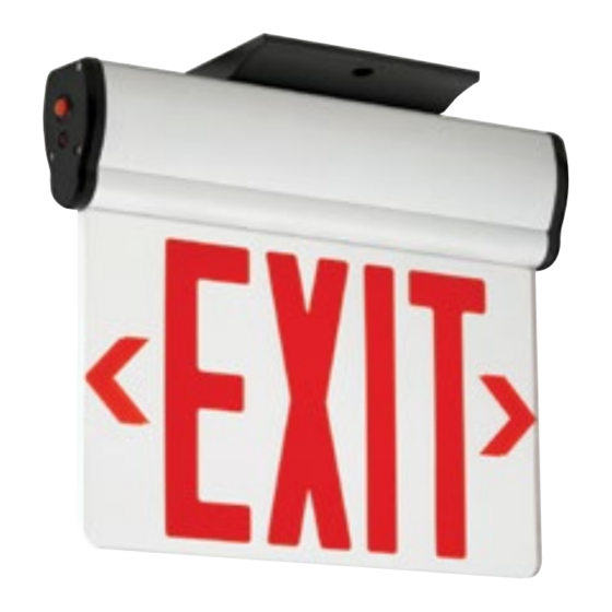
LED Edge-Lit EXIT Sign
LED Edge-Lit EXIT Sign
1
1
Canopy
Canopy
1
1
Hardware Bag
1
Hardware Bag
1
CELS
CELS
Surface Mount LED Emergency Exit
Surface Mount LED Emergency Exit
Hubbell Lighting, Inc.
Advertisement
Table of Contents

Related Manuals for Current COMPASS CELS


Summary of Contents for Current COMPASS CELS
- Page 1 •SAVE THESE INSTRUCTIONS FOR USE BY OWNER/OCCUPANT WARNING – This product contains chemicals known to the State of California to cause cancer, birth Current Lighting Solutions, LLC WARNING – This product contains chemicals known to the State of California to cause cancer, birth defects and/or other reproductive harm.
- Page 2 INSTALLATION INSTALLATION INSTALLATION INSTALLATION INSTALLATION INSTALLATION ASSEMBLY DRAWING ASSEMBLY DRAWING INSTALLATION 6. Peel off protective film from both sides of EXIT panel INSTALLATION ASSEMBLY DRAWING INSTALLATION INSTALLATION Insert EXIT panel into main body assembly gently. If EXIT panel is for single ASSEMBLY DRAWING ASSEMBLY DRAWING INSTALLATION...
Need help?
Do you have a question about the COMPASS CELS and is the answer not in the manual?
Questions and answers