
Subscribe to Our Youtube Channel
Related Manuals for VALCO MELTON VCX


Summary of Contents for VALCO MELTON VCX
- Page 1 VCX Service Manual For Internal Use Only Manual Number: MC083 Revision Date: 5/2022...
- Page 2 Valco Cincinnati, Inc. This manual written and designed at Valco Melton, 497 Circle Freeway Drive, Suite 490, Cincinnati, Ohio 45246. http://www.valcomelton.com Part Number: MC083 Written and printed in the USA.
- Page 3 Hortonwood 32 Agustinos Telford TF1 7YN England calle G, n. 34 31160 Orcoyen Navarra, Spain declares that the product: Product Name: VCX Service Manual complies with the following Council Directives: Safety of Machinery: 2006/42/EC Low Voltage Equipment: 2014/35/EU EMC: 2014/30/EU...
-
Page 5: Table Of Contents
MC083 - VCX Service Manual Table of Contents Table of Contents Table of Contents ....................5 Section 1 - Introduction ..................9 Section 2 - Safety and Use ..................11 Read Thoroughly Before Handling Equipment ......................11 Symbols ..................................11 Owner Responsibilities .............................. - Page 6 Top Switch Function Label ........................61 Mounting Bracket for OT-120 Control ....................62 Section 4 - Setup ....................63 Adding Modules ................................63 Removing the Cover of the VCX Control ....................63 Add Modules ............................64 Remove Modules ............................ 65 System Layout Example Illustration ...........................66 Bracket Mounting Patterns ............................67...
- Page 7 Notes regarding OT and TCM ............................ 82 Section 6 - Part Number List ................. 83 How to Order Parts ..............................83 VCX-4 Control Base (074xx042) ..........................84 Power Supply Module (148xx063) ..........................86 Pattern Control Module with EPC (074xx043) ......................88 Pattern Control Module with EPC;...
- Page 8 Table of Contents MC083 - VCX Service Manual Appendix A - Parameters ..................131 Appendix B - Test and Diagnostic Monitor ............201 System Requirements ..............................201 Hyperterminal Setup ..............................201 Monitor Functions ................................203 Boot Message ............................203 Help Function............................203 Print Parameter Function ............................204 Use the Disk Utilities for Unit Data Recovery ......................205...
-
Page 9: Section 1 - Introduction
Section 1 - Introduction Section 1 - Introduction The VCX Control is a modular, integrated system for gluing control and quality assurance. Pattern Control Modules, Inspection Control Modules, and Tracking/Ejecting Modules can be combined with one or two VCX Controls to provide all functions of glue application, inspection, and quality assurance. - Page 10 Section 1 - Introduction MC083 - VCX Service Manual...
-
Page 11: Section 2 - Safety And Use
MC083 - VCX Service Manual Section 2 - Safety and Use Section 2 - Safety and Use Read Thoroughly Before Handling Equipment WARNING! Read and follow all safety precautions, warnings, cautions, and other recommendations in this manual. OTHERWISE, DEATH, PERSONAL INJURY OR EQUIPMENT DAMAGE COULD OCCUR. -
Page 12: Owner Responsibilities
Do not use this equipment for anything other than its intended use. Do not modify, change, or alter the equipment in any way. If you are unsure of the intended use and the limitations of use for the equipment, contact your Valco Melton... -
Page 13: Installation/Startup/Use Safety Information
Section 2 - Safety and Use Installation/Startup/Use Safety Information Valco Melton hot melt units, cold glue units, controllers, inspection systems and all related accessories have the following universal safety precautions (this is not intended to be an exhaustive list; follow all instructions and safety... -
Page 14: Shut Down Safety Information
MC083 - VCX Service Manual Shut Down Safety Information Valco Melton hot melt units, cold glue units, controllers, inspection systems and all related accessories have the following universal safety precautions (this is not intended to be an exhaustive list; follow all instructions and safety... -
Page 15: What To Do If Contact With Hot Adhesive Occurs
MC083 - VCX Service Manual Section 2 - Safety and Use WARNING! People with respiratory problems (e.g., asthma, bronchitis, etc.) should not work in the vicinity of molten adhesive. RESPIRATORY PROBLEMS MAY BE AGGRAVATED BY THE FUMES. Do not wear a face mask when working around molten adhesive. THE MASK MAY TRAP THE FUMES AND DEATH OR PERSONAL INJURY COULD OCCUR. -
Page 16: What To Do If Adhesive-Related Fire Or Explosion Occurs
Section 2 - Safety and Use MC083 - VCX Service Manual What to Do if Adhesive-Related Fire or Explosion Occurs During the heating and melting process, the surface of the adhesive will be exposed to air. The mixture of polymer fumes and air can catch fire if the hot melt is overheated. -
Page 17: Hose Safety Information
MC083 - VCX Service Manual Section 2 - Safety and Use Hose Safety Information DO NOT Do not use bindings, wire Do use approved ties, or unapproved wrapping (P/N fasteners around the KAP0434), making sure hoses. the wrapping is slightly snug but not tight. - Page 18 Section 2 - Safety and Use MC083 - VCX Service Manual...
-
Page 19: Section 3 - Basic Features
Section 3 - Basic Features VCX Control The VCX Control consists of a Power Supply Module (148xx063) in a base assembly. Four slots are available in the base assembly for additional modules. Module choices include Pattern Control Modules (PCM), Inspection Control Modules (ICM), Tracking Control Modules with Ejector (TCM-E), and Color Code Reader (CDS). -
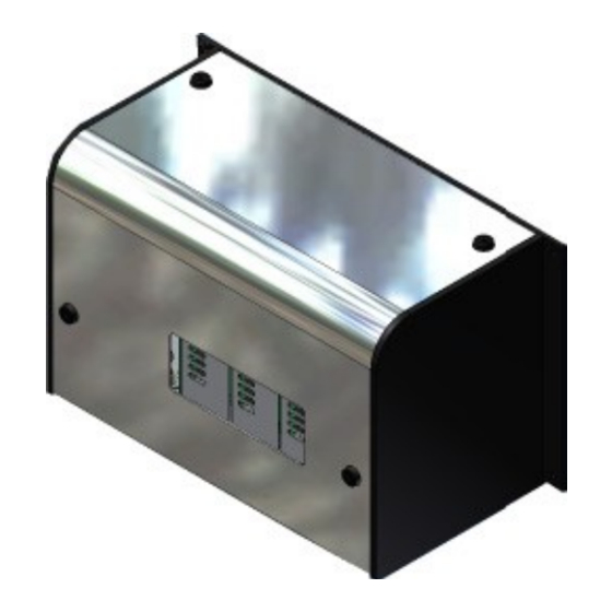
Page 20: Vcx Specifications
Section 3 - Basic Features MC083 - VCX Service Manual VCX Specifications DIMENSIONS AND WEIGHT SIZE Width 19" [482.6mm] Height 12"[304.8mm] Depth 9.5"[241.3mm] WEIGHT Overall weight is dependent on the configuration. Base unit weight 33lb (15kg), Module weight @ 4.5lb (2kg) - Page 21 MC083 - VCX Service Manual Section 3 - Basic Features Power Supply Module - Continued Power Supply Module Features Status LEDs: Number Name Power Supply Pump/Alarm Power Supply Encoder Power Supply Terminal Line Voltage Selection 115/230 Relay Power Supply Module Features...
-
Page 22: Power Supply Module Connector Pinouts
Section 3 - Basic Features MC083 - VCX Service Manual Power Supply Module Connector Pinouts Terminal Port Connector 7 Terminal Port Pin # Description CAN - Low CAN - High P Button + P Button - Remote Out + Pinout Drawing for Connector 7... -
Page 23: Control Link Port
MC083 - VCX Service Manual Section 3 - Basic Features Control Link Port Connector 8 Control Link Port Pin # Description CAN - Low CAN - Ground CAN - High Remote – Out + CAN +5V Pinout Drawing for Connector 8... -
Page 24: Encoder Connections - Female/Input
Section 3 - Basic Features MC083 - VCX Service Manual Encoder Connections - Female/Input Connector 10 Encoder Connections Pin # Description Color Ground Black A Signal Orange +24V/+12V B Signal Yellow Z Signal Brown /Z Signal Violet /B Signal Blue... -
Page 25: Beacon/Alarm Connection
MC083 - VCX Service Manual Section 3 - Basic Features Beacon (Alarm) Connection Connector 12 Beacon/Alarm Connection Pin # Description Color Ground Brown Light (Glue) White Light (Jam) Blue Buzzer Black Light (LLD) Shield/Gray Pinout Drawing for Connector 12 Relay Feed Stop Connection... -
Page 26: Pattern Control Module (Pcm)
Section 3 - Basic Features MC083 - VCX Service Manual Pattern Control Module (PCM) The back of the module may vary depending on the options and the style of the module. Two examples are illustrated above. - Page 27 MC083 - VCX Service Manual Section 3 - Basic Features Pattern Control Module (PCM) - Continued Pattern Control Module Features Status LEDs: Number Name/Description Supply Scanner/Logic (1 and 2) CAN –S - Illuminates steady green when two-way communication is occurring. Flashes green when the communication channel is open but a signal is not being received at the present time.
-
Page 28: Pattern Control Module Connector Pinouts
Section 3 - Basic Features MC083 - VCX Service Manual Pattern Control Module Connector Pinouts Valve Connections Connector 10 Valve Connections Pin # Description Color Coil Brown Coil White Purge Blue Purge Black PE (Shield) Green/Yellow Pinout Drawing for Connector 10... -
Page 29: Epc 2 Connection
MC083 - VCX Service Manual Section 3 - Basic Features EPC 2 Connection Connector 12 EPC 2 Connection Pin # Description Color +24V Brown OV (Signal) White Ground Blue Black 0-20 mA Shield Shield/Grey Pinout Drawing for Connector 12 *Can be switched to 0-10V via software... -
Page 30: Valve Junction Box (E-Box) Port
Section 3 - Basic Features MC083 - VCX Service Manual Valve Junction Box (E-Box) Port Connector 15 Valve Junction Box Port Pin # Description Valve 1 – Coil + Valve 1 – Coil - Valve 2 – Coil + Valve 2 – Purge + Valve 2 –... -
Page 31: Inspection Control Module (Icm)
MC083 - VCX Service Manual Section 3 - Basic Features Inspection Control Module (ICM) -
Page 32: Sensor Adapter Modules
Section 3 - Basic Features MC083 - VCX Service Manual Sensor Adapter Modules Different sensor adapter modules are available for use in the Inspection Control Module. These modules slide in as shown below: The modules available are: AS 601 151xx501... -
Page 33: Inspection Control Module Connector Pinouts
MC083 - VCX Service Manual Section 3 - Basic Features Inspection Control Module (ICM) - Continued Inspection Control Module Features Connectors: Number Name RS-232 Port Sensor Connection (1-4) Marking Valve Connection Sensor Connection (1-2) Sensor Connection (3-4) Inspection Control Module Features... -
Page 34: Marking Valve Connection
Section 3 - Basic Features MC083 - VCX Service Manual Marking Valve Connection Connector 12 Marking Valve Connection Pin # Description Color Coil Brown Coil White Purge Blue Purge Black PE (Shield) Grey Pinout Drawing for Connector 12 Scanner Connection... -
Page 35: Sensors 1-2 (J-Box) Connections
MC083 - VCX Service Manual Section 3 - Basic Features Sensors 1-2 (J-Box) Connections Connector 13 Sensor Connections 1 & 2 Pin # Description Sensor 1 - 1 Sensor 1 – 2 Sensor 1 – 3 Sensor 1 – 4 Sensor 1 –... -
Page 36: Sensors 3-4 (J-Box) Connections
Section 3 - Basic Features MC083 - VCX Service Manual Sensors 3-4 (J-Box) Connections Connector 14 Sensor Connections 3 & 4 Pin # Description Sensor 3 – 1 Sensor 3 – 2 Sensor 3 – 3 Sensor 3 – 4 Sensor 3 –... -
Page 37: Tracking Control Module (Tcm) - Cube/X49
MC083 - VCX Service Manual Section 3 - Basic Features Tracking Control Module (TCM) - Cube/X49... - Page 38 Section 3 - Basic Features MC083 - VCX Service Manual Tracking Control Module (TCM) - Cube/X49 - Continued Tracking Control Module Features - Cube/X49 Status LEDs: Number Name Counter Power Supply CAN Status Power Supply Scanner Scanner Status (1-3) CDS Power Supply...
-
Page 39: Tracking Control Module Connector Pinouts - Cube/X49
MC083 - VCX Service Manual Section 3 - Basic Features Tracking Control Module Connector Pinouts - Cube/X49 Sync Scanner Connection Connector 14 Sync Scanner Connections Pin # Description Color +24V Brown White Ground Blue Black Shield Shield/Grey Pinout Drawing for Connector 14 CDS Sensor 1 and 2 Connection Connectors 15 &... -
Page 40: Cube/X49 Connector (Bobst)
Section 3 - Basic Features MC083 - VCX Service Manual Cube/X49 Connector (Bobst) Connector 17 Cube/X49 Connector (Bobst) Description Pin # Sensor 6 (cube) Sensor 5 (cube) Sensor 4 (cube) Sensor 6 (cube) Sensor 3 (cube) Sensor 5 (cube) SENSOR 2 – Valco Sensor 4 (cube) SENSOR 1–... -
Page 41: Tracking Control Module (Tcm) - Flipper Ejector
MC083 - VCX Service Manual Section 3 - Basic Features Tracking Control Module (TCM) - Flipper Ejector... - Page 42 Section 3 - Basic Features MC083 - VCX Service Manual Tracking Control Module (TCM) - Flipper Ejector - Continued Tracking Control Module Features - Flipper Status LEDs: Number Name Counter Power Supply CAN Status Power Supply Scanner Scanner Status (1-3)
-
Page 43: Tracking Control Module Connector Pinouts - Flipper
MC083 - VCX Service Manual Section 3 - Basic Features Tracking Control Module Connector Pinouts - Flipper Counter Output Connection Connector 18 Counter Output Pin # Description Color Brown Count N.O. White Blue Count N.C. Black Shield Shield/Grey Pinout Drawing for Connector 18... -
Page 44: Cds Connection
Section 3 - Basic Features MC083 - VCX Service Manual CDS Connection Connectors 20 & 24 CDS Sensor 1 and 2 Pin # Description Color +24V White ENC-A Brown ENC-Ā Green CAN-Low Yellow CAN-High Grey Pink +24V Blue Sync Result... -
Page 45: Tracking Control Module (Tcm) - Sprayer/Kicker
MC083 - VCX Service Manual Section 3 - Basic Features Tracking Control Module (TCM) - Sprayer/Kicker 074xx052 Tracking Control Module Features - Sprayer/Kicker Status LEDs: Number Name Counter Power Supply CAN Status Power Supply Scanner Scanner Status (1-2) CDS Power Supply... - Page 46 Section 3 - Basic Features MC083 - VCX Service Manual Tracking Control Module Features - Sprayer/Kicker Connectors: Number Name Counter Output Scanner 1 CDS 1 Spray Valve Scanner 2 CDS 2 Tracking Control Module Features - Sprayer/Kicker Fuses: Number Fuse Type Part No.
-
Page 47: Tracking Control Module Connector Pinouts - Sprayer/Kicker
MC083 - VCX Service Manual Section 3 - Basic Features Tracking Control Module Connector Pinouts - Sprayer/Kicker Counter Output Connection Connector 18 Counter Output Pin # Description Color +24V Brown White Ground Blue Black Shield Shield/Gray Pinout Drawing for Connectors 18... -
Page 48: Cds Connection
Section 3 - Basic Features MC083 - VCX Service Manual CDS Connection Connectors 20 & 24 CDS Sensor 1 & 2 Pin # Description Color +24V White ENC-A Brown ENC-A Green CAN-Low Yellow CAN-High Gray Pink +24V Blue Sync Result... -
Page 49: Spray Valve Connection
MC083 - VCX Service Manual Section 3 - Basic Features Spray Valve Connection Connector 21 Flipper Pin # Description Color Coil Brown Coil White Purge Black Purge Black PE (shield) Gray Pinout Drawing for Connectors 20 & 24... -
Page 50: Tracking Control Module (Tcm) - Mars Ejector
Section 3 - Basic Features MC083 - VCX Service Manual Tracking Control Module (TCM) - MARS Ejector... - Page 51 MC083 - VCX Service Manual Section 3 - Basic Features Tracking Control Module (TCM) - MARS Ejector - Continued Tracking Control Module Features - MARS Ejector Status LEDs: Number Name Counter Power Supply CAN Status Power Supply Scanner Scanner Status (1-3)
-
Page 52: Tracking Control Module Connector Pinouts - Mars Ejector
Section 3 - Basic Features MC083 - VCX Service Manual Tracking Control Module Connector Pinouts - MARS Ejector Counter Output Connection Connector 18 Counter Output Pin # Description Color Brown Count N.O. White Blue Count N.C. Black Shield Shield/Gray Pinout Drawing for Connectors 18... -
Page 53: Cds Connections 1 & 2
MC083 - VCX Service Manual Section 3 - Basic Features CDS Connections 1 & 2 Connectors 20 & 24 CDS Sensor 1 & 2 Pin # Description Color +24V White ENC-A Brown ENC-A Green CAN-Low Yellow CAN-High Gray Pink +24V... -
Page 54: Ejector Control Connection
Section 3 - Basic Features MC083 - VCX Service Manual Ejector Control Connection Connector 26 Ejector Control Pin # Description Color 0-10V Brown White EJ - Enable (+) Black EJ - Enable (-) Black EJ - Stat (+) Gray EJ - Stat (-) -
Page 55: Ejector Power Supply Connection
MC083 - VCX Service Manual Section 3 - Basic Features Ejector Power Supply Connection Connector 28 Ejector Power Supply Pin # Description 230VAC (L) 230VAC (N) Pinout Drawing for Connectors 28... -
Page 56: Ot-120 Terminal
Section 3 - Basic Features MC083 - VCX Service Manual OT-120 Terminal... - Page 57 MC083 - VCX Service Manual Section 3 - Basic Features OT-120 Terminal - Continued OT-120 Features LEDs: Number Name Consecutive Faults LED (Illuminates when the [programmed] maximum number of consecutive faults is reached.)* Power On LED *Available for MCU only.
-
Page 58: Ot-120 Terminal Connector Pinouts
Section 3 - Basic Features MC083 - VCX Service Manual OT-120 Terminal Connector Pinouts COM Port Connection Connector 7 COM Port Pin # Description Pinout Drawing for Connector 7... -
Page 59: Can Port Connection
MC083 - VCX Service Manual Section 3 - Basic Features CAN Port Connection Connector 8 COM Port Pin # Description CAN-Low CAN-GND* CAN-High Remote-Out Pinout Drawing for Connector 8 *Only with JPI Closed... -
Page 60: Power/Control Port Connection
Section 3 - Basic Features MC083 - VCX Service Manual Power/Control Port Connection Connector 9 Power/Control Port Pin # Description CTS- CTS+ RX485+ RX485- TX485+ TX485- Remote in 2 MCU Enable PButton+ PButton- RTS- RTS+ MCU MStop Remote Out +... -
Page 61: Top Switch Function Label
MC083 - VCX Service Manual Section 3 - Basic Features Top Switch Function Label Switch Description Default Setting Unit MCU/VCX Switches between MCU and VCX CAN 2 120 Ohm Off/On Not Connected Switches CAN 1 Off or On CAN 1 120 Ohm Off/On... -
Page 62: Mounting Bracket For Ot-120 Control
Section 3 - Basic Features MC083 - VCX Service Manual Mounting Bracket for OT-120 Control The mounting bracket for the OT-120 allows the operator to swivel the control for best viewing. See the Part Number List Section for more details. -
Page 63: Section 4 - Setup
PERSONAL INJURY, AND/OR EQUIPMENT DAMAGE. To remove the cover of the VCX Control, use a hex wrench to turn the hex latches 1/2 turn to unhook the 4 latches that lock the cover onto the base (see Figure 4-1). Carefully remove the cover by grasping the cover “cup” handle and lifting the cover off of the unit. -
Page 64: Add Modules
Do not apply excessive force and do not use tools to seat the module! Damage to the equipment may result. 3. Slide the module into the VCX Control base as shown in Figure 4-2. Make sure the module slides in easily. Pay attention to the connector and make sure the locator pin matches up with the mating connector. -
Page 65: Remove Modules
2. Disconnect all cables/plugs from the back of the module. 3. Loosen the screws that secure the module to the base rails of the VCX Control base (see Figure 4-2). 4. Slide the module out of the VCX Control base (see Figure 4-2). -
Page 66: System Layout Example Illustration
Section 4 - Setup MC083 - VCX Service Manual System Layout Example Illustration 030X X738 10 METER S TD . KEY Exhaust Exhaust... -
Page 67: Bracket Mounting Patterns
MC083 - VCX Service Manual Section 4 - Setup Bracket Mounting Patterns All mounting patterns are enlarged to show detail. VCX Control OT-120 Panel Mount... -
Page 68: Epp-6 Pump
Section 4 - Setup MC083 - VCX Service Manual EPP-6 Pump 3:1 Balancing Regulator... -
Page 69: Linking Two Vcx Controls
5. Set the Control Selector Switch on “VCX -2” to “2” (see Figure 4-3). 6. Replace the covers on both VCX Controls (see Figure 4-1). 7. Connect the cables on the “VCX -1,” the “VCX -2,” and the OT-120 Unit as shown in Figure 4-4. 8. Reconnect the power. - Page 70 Section 4 - Setup MC083 - VCX Service Manual Linking Two VCX Controls -Continued The encoders can be linked together as shown above. Figure 4-4. Connecting the Cables...
-
Page 71: Cds Color-Code Reader
MC083 - VCX Service Manual Section 4 - Setup CDS Color-Code Reader Figure 4-5. CDS Camera - Operator Side (SB3001) Description The CDS Color-Code Reader is a versatile tool that provides the following high-speed inspection functions: mixed copy, missing color and color density, print registration, die-cut registration (lateral and longitudinal), and skewed cartons and double feeds. -
Page 72: Cds Connection Layout
Section 4 - Setup MC083 - VCX Service Manual CDS Connection Layout The figure below shows the basic system configuration for the CDS, including cables and key components. Figure 4-6. CDS Connection Layout... -
Page 73: Cds Control Box Pinouts
MC083 - VCX Service Manual Section 4 - Setup CDS Control Box Pinouts Figure 4-7. CDS Control Box Pinouts VCX Control Pin# Description + 24 VDC (A) ENCODER IN (1A) ENCODER IN CAN LOW CAN HIGH GROUND + 24 VDC... -
Page 74: Head Trigger
Section 4 - Setup MC083 - VCX Service Manual Head Trigger Pin# Description + 5 VDC EXTERNAL SCANNER DETECT EXTERNAL SCANNER (NPN) GROUND GROUND GROUND PHOTODIODE NO CONNECT NO CONNECT Head Lamp Pin# Description + 12 VDC (LAMP) + 12 VDC (LAMP) -
Page 75: Head Signals
MC083 - VCX Service Manual Section 4 - Setup Head Signals Pin# Description RED -GROUND RED-IN GREEN - GROUND GREEN - IN BLUE - GROUND BLUE - IN + 15 VDC CDS -GROUND - 15 VDC LED ONLY OUT NO CONNECT... -
Page 76: White Value Calibration Procedure
Section 4 - Setup MC083 - VCX Service Manual White Value Calibration Procedure The White Value Adjustment feature is only needed when the system is started at the time of installation, or after changing the halogen lamp in the CDS sensor. The purpose for the procedure is to establish a base point by which the system determines the true value of white. -
Page 77: Code-Reading Hints
MC083 - VCX Service Manual Section 4 - Setup Establishing a Baseline for the CDS Sensor - Continued It is important to sample with a carton that has been checked for good quality because all of the remaining cartons will be compared to the master carton. -
Page 78: Wheel-Driven Encoder
Section 4 - Setup MC083 - VCX Service Manual Wheel-Driven Encoder If using a wheel-driven encoder (Figure 5-6), a VDD-1000 encoder with a 10-inch measuring wheel is recommended. To install a wheel-driven encoder, follow these steps: 1. Mount the encoder’s bracket to the frame of the parent machine. - Page 79 MC083 - VCX Service Manual Section 4 - Setup Gear-Driven Encoder - Continued Figure 4-10. Typical Installation of a Gear-Driven Encoder...
- Page 80 Section 4 - Setup MC083 - VCX Service Manual...
-
Page 81: Section 5 - Operation
Figure 5-1. Turn on the OT-120 Unit 2. Plug in the VCX. 3. Flip the power switch on the back of the VCX Power Supply Module to the “On” position (see Figure 5-2). Figure 5-2. VCX Power Supply Module Power Switch... -
Page 82: Power Down Sequence
3. Wait until the standby LED on the OT-120 Control turns orange as the unit powers down (see Figure 5-1). 4. Flip the power switch on the back of the VCX Power Supply Module to the “Off” position (see Figure 5-2). -
Page 83: Section 6 - Part Number List
MC083 - VCX Service Manual Section 6 - Part Number List Section 6 - Part Number List How to Order Parts To order parts, please contact your closest Valco office by mail, phone, or Email: Valco Cincinnati, Inc. 497 Circle Freeway Drive... -
Page 84: Control Base (074Xx042)
Section 6 - Part Number List MC083 - VCX Service Manual VCX-4 Control Base (074xx042) - Page 85 023XX101 FLAT WASHER 884XX039 SCREW 784XX653 INSTALLATION KIT ASSY,VCX 091XX624 GASKET,TRANSFORMER 746XX174 It is not necessary to place a module in every slot of the VCX Control base. A blank module cover (026xx211) is used to cover each empty slot.
-
Page 86: Power Supply Module (148Xx063)
Section 6 - Part Number List MC083 - VCX Service Manual Power Supply Module (148xx063) - Page 87 MC083 - VCX Service Manual Section 6 - Part Number List Power Supply Module (148xx063) - Continued Item Description Part Number Quantity PCB SUBA POWER-SUPPLY VCX 152XX655 CABLE ASSY,RELAY CONTACTS,VCX 029XX399 CABLE ASSY,PUMP CONN,VCX 029XX398 CABLE ASSY 029XX397 PCB ASSY CONN OT/CAN VCX...
-
Page 88: Pattern Control Module With Epc (074Xx043)
Section 6 - Part Number List MC083 - VCX Service Manual Pattern Control Module with EPC (074xx043) - Page 89 MC083 - VCX Service Manual Section 6 - Part Number List Pattern Control Module with EPC (074xx043) - Continued Item Description Part Number Quantity PCB Assembly, PCM-4, VCX 151xx619 PCB Assembly, CPU32MOD, VCX 152xx698 Cable Assembly, P M12 F T0 5P MCT...
-
Page 90: Pattern Control Module With Epc; Junction Box (E Box) Port (074Xx044)
Section 6 - Part Number List MC083 - VCX Service Manual Pattern Control Module with EPC; Junction Box (E Box) Port (074xx044) - Page 91 MC083 - VCX Service Manual Section 6 - Part Number List Pattern Control Module with EPC; Junction Box (E Box) Port (074xx044) - Continued...
- Page 92 Section 6 - Part Number List MC083 - VCX Service Manual Pattern Control Module with EPC; Junction Box (E Box) Port (074xx044) - Continued Item Description Part Number Quantity PCB Assembly, PCM4 Application 151xx619 PCB Assembly, CPU32MOD, VCX 151xx631 Cable Assembly, E-box Scanner...
-
Page 93: Pattern Control Module Without Epc (074Xx050)
MC083 - VCX Service Manual Section 6 - Part Number List Pattern Control Module without EPC (074xx050) 074xx050.DWG... - Page 94 Section 6 - Part Number List MC083 - VCX Service Manual Pattern Control Module without EPC (074xx050) - Continued Item Description Part Number Quantity PCB Assembly, PCM4, VCX 151xx619 PCB Assembly, CPU32MOD, VCX 151xx631 Cable Assembly, 5P M12 F to 5P MCT...
- Page 95 MC083 - VCX Service Manual Section 6 - Part Number List Pattern Control Module without EPC; Junction Box (E Box) Port (074xx051)
- Page 96 Section 6 - Part Number List MC083 - VCX Service Manual Pattern Control Module without EPC; Junction Box (E Box) Port (074xx051) - Continued Item Description Part Number Quantity PCB Assembly, PCM$, Application 151xx619 PCB Assembly, CPU32MOD, VCX 151xx631 Cable Assembly, E-box Scanner...
-
Page 97: Inspection Control Module (074Xx065)
MC083 - VCX Service Manual Section 6 - Part Number List Inspection Control Module (074xx065) - Page 98 Section 6 - Part Number List MC083 - VCX Service Manual Inspection Control Module (074xx065) - Continued Item Description Part Number Quantity PCB,ASSY,INSPECTION,4CH,VCX 151XX620 PCB,SUB-ASSY,CPU32,TURBO,VCX 152XX698 CABLE ASSY 029XX426 CABLE ASSY 029XX396 RIBBON CABLE ASSY 033XX166 MODULE-FRAME,INSPECTION 026XX227 SCREW 784XX985...
-
Page 99: Adapter Modules
MC083 - VCX Service Manual Section 6 - Part Number List Adapter Modules Different sensor adapter modules are available for use in the Inspection Control Module. These modules slide in as shown below: BAWadapters.DWG The modules available are: AS 601... -
Page 100: Tracking Control Module - Tcmej (074Xx049)
Section 6 - Part Number List MC083 - VCX Service Manual Tracking Control Module - TCMEJ (074xx049) 151XX648 REV-A... - Page 101 MC083 - VCX Service Manual Section 6 - Part Number List Tracking Control Module - TCM-EJ (074xx049) - Continued 310V C UBE X4 9 240VAC 1 / O...
- Page 102 Section 6 - Part Number List MC083 - VCX Service Manual Tracking Control Module - TCM-EJ (074xx049) - Continued Item Description Part Number Quantity PCB ASSY TRACK-CNTRL EJECT VCX 151XX638 BHCS M4 X 6 SS 784XX985 WASHER LOCK M3 EXT-TOOTH 784XX315 FRAME, MODULE: TRACKING MOD.
-
Page 103: Tracking Control Module - Tcmf (074Xx048)
MC083 - VCX Service Manual Section 6 - Part Number List Tracking Control Module - TCMF (074xx048) - Page 104 Section 6 - Part Number List MC083 - VCX Service Manual Tracking Control Module - TCM-F (074xx048) - Continued Item Description Part Number Quantity PCB Assembly, Track Cont.-Ejector TSW0777 BHSC Screw 784xx985 Lock Washer, M3 784xx315 Module, Frame BAW1390 Plate Rear...
-
Page 105: Tracking Control Module - Tcmcube/49 (074Xx047)
MC083 - VCX Service Manual Section 6 - Part Number List Tracking Control Module - TCMCube/49 (074xx047) - Page 106 Section 6 - Part Number List MC083 - VCX Service Manual Tracking Control Module - TCMCube/49 (074xx047) - Continued...
- Page 107 MC083 - VCX Service Manual Section 6 - Part Number List Tracking Control Module - TCMCube/49 (074xx047) - Continued Item Description Part Number Quantity PCB ASSY, TRACKING,X49,VCX 151XX659 SCREW 784XX985 LOCK WASHER 784XX308 FRAME, MODULE: TRACKING MOD. 026XX262 PLATE, REAR CONNECTOR MTG.
-
Page 108: Junction Box (029Xx439)
Section 6 - Part Number List MC083 - VCX Service Manual Junction Box (029xx439) - Page 109 MC083 - VCX Service Manual Section 6 - Part Number List Junction Box (029xx439) - Continued Item Description Part Number Quantity Connector, D-sub, Male 061xx398 Housing, Cable Conn., D-sub, 37P 061xx406 Tubing 755xx028 Junction Box, 4 Valves, 5M 029xx441 Tubing...
-
Page 110: Junction Box (029Xx440)
Section 6 - Part Number List MC083 - VCX Service Manual Junction Box (029xx440) - Page 111 MC083 - VCX Service Manual Section 6 - Part Number List Junction Box (029xx440) - Continued Item Description Part Number Quantity Housing, D-sub, 15P, Cable 061xx288 Connector, D-sub, 15M 061xx289 Tubing 755xx028 Junction Box, 4 Scanners, 5M 029xx442 Socket Head Cap Screw, M4 X 25 SS...
-
Page 112: Panel Mount Ot-120 (138Xx019)
Section 6 - Part Number List MC083 - VCX Service Manual Panel Mount OT-120 (138xx019) Item Description Part Number Quantity SBC,OMAP3703,800MHZ,512M DDR 151XX704 DISPLAY/TOUCH ASSY,OT-120 138XX022 PCB ASSY INTERF VT/DSP OT-120 151XX705 CABLE, LVDS, 20PIN, 18" LONG 029XX690 PLATE ASSEMBLY - OT-120... - Page 113 MC083 - VCX Service Manual Section 6 - Part Number List Panel Mount OT-120 (138xx019) - Continued Item Description Part Number Quantity PLATE ASSEMBLY - OT-120 026XX380 GASKET,OT-120 TOUCHSCREEN 746XX157 ENCLOSURE ASSEMBLY - OT-120 026XX381 CABLE ASSY, OT, SWITCH 029XX713...
-
Page 114: Standard Ot-120 (138Xx018)
Section 6 - Part Number List MC083 - VCX Service Manual Standard OT-120 (138xx018) - Page 115 MC083 - VCX Service Manual Section 6 - Part Number List Standard OT-120 (138xx018) - Continued Item Description Part Number Quantity SBC,OMAP3703,800MHZ,512M DDR 151XX704 DISPLAY/TOUCH ASSY,OT-120 138XX022 PCB ASSY INTERF VT/DSP OT-120 151XX705 CABLE, LVDS, 20PIN, 18" LONG 029XX690 PLATE ASSEMBLY, OT-120...
- Page 116 Section 6 - Part Number List MC083 - VCX Service Manual Standard OT-120 (138xx018) - Continued Item Description Part Number Quantity FHSS M4 X 10 SS 784XX190 MEMORY CARD SD 512MB SLC 118XX204 SCREW,JACK,HEX,4-40,12MM 091XX267 SHCS M3 X 10MM SEMS TYPE...
-
Page 117: Panel Mount Ot-120 - Previous Version (138Xx008)
MC083 - VCX Service Manual Section 6 - Part Number List Panel Mount OT-120 - previous version (138xx008) 138xx008.DWG... - Page 118 Section 6 - Part Number List MC083 - VCX Service Manual Panel Mount OT-120 - previous version (138xx008) - Continued Item Description Part Number Quantity PCB Assembly, VGX2594 151xx607 Touchpanel/Display Assembly, OT-120 138xx005 PCB Assembly, Interface, OT-120 151xx654 Plate Assembly...
- Page 119 MC083 - VCX Service Manual Section 6 - Part Number List Standard OT-120 - previous version (138xx007)
- Page 120 Section 6 - Part Number List MC083 - VCX Service Manual Standard OT-120 - previous version (138xx007) - Continued...
- Page 121 MC083 - VCX Service Manual Section 6 - Part Number List Standard OT-120 - previous version (138xx007) - Continued Item Description Part Number Quantity PCB Assembly, VGX2594 151xx607 Touchpanel/Display Assembly, OT-120 138xx005 PCB Assembly, Interface, OT-120 151xx654 Front Mounting Plate...
-
Page 122: Cables
Section 6 - Part Number List MC083 - VCX Service Manual Cables OT-120 Cables Description Part Number OT-120 Cable, 2m 029xx331 OT-120 Cable, 5m 029xx126 OT-120 Cable, 10m 029xx147 OT-120 Cable, 15m 029xx159 OT-120 Cable, 20m 029xx160... -
Page 123: Scanner Cables
MC083 - VCX Service Manual Section 6 - Part Number List Scanner Cables... -
Page 124: Link Cables
Section 6 - Part Number List MC083 - VCX Service Manual Link Cables Description Part Number Link Cable, 3m 029xx418 Link Cable, 6m 029xx417... -
Page 125: Valve Cables
MC083 - VCX Service Manual Section 6 - Part Number List Valve Cables CDS Color-Code Reader Description Part Number Color-code sensor CDS, mounted with sensor SB3000 SB3200 SB3300 SB300041 Guide metal sheet and 2 IS screws (M5 x 20) SB340011... -
Page 126: Cds Control Box (098Xx102-01)
Section 6 - Part Number List MC083 - VCX Service Manual CDS Control Box (098xx102-01) - Page 127 MC083 - VCX Service Manual Section 6 - Part Number List CDS Control Box (098xx102-01) - Continued ITEM DESCRIPTION PART # ENCLOSURE MODIFICATION 026XX284 PCB ASSY PROCESSOR CDS SENSOR 152XX662 PLATE, FRONT DISPLAY 026XX285 SCREW 798XX485 LABEL, CDS CONTROL BOX...
- Page 128 Section 6 - Part Number List MC083 - VCX Service Manual...
-
Page 129: Section 7 - Button Configurations
MC083 - VCX Service Manual Section 7 - Button Configurations Section 7 - Button Configurations Password Access Configuration To access the Password Access Configuration Dialog, do the following: 1. From the Main Menu Screen, press the General Setup Button. The General Setup Screen appears (see Figure 8-1). - Page 130 Section 7 - Button Configurations MC083 - VCX Service Manual Password Access Configuration - Continued 4. The switch in the selection window will be off (default setting). Pressing the switch will turn it on, enabling the Icon Configuration function. 5. Press Confirm to close the dialog. The system will now allow Icon configuration.
- Page 131 MC083 - VCX Service Manual Appendix A - Parameters Appendix A - Parameters DS-CDS Index Sub- Name Object Data Access Comment Default (Hex) Index Type Type Type (Hex) 3000 Software Version VSTR Complete software © VALCO version and copyright Cincinnati, information Inc.
- Page 132 Appendix A - Parameters MC083 - VCX Service Manual DS-CDS Index Sub- Name Object Data Access Comment Default (Hex) Index Type Type Type (Hex) 300E Status/Code for Size = 4 Bytes; Bytes Last Message 0-1 = Error/Message, Byte2 = Error Code,...
- Page 133 MC083 - VCX Service Manual Appendix A - Parameters DS-CDS Index Sub-Index Name Object Data Access Type Comment Default (Hex) (Hex) Type Type Consecutive 0 = No Output Fault Alarm - 1 = Relay 1 Output 1 2 = Relay 2...
- Page 134 Appendix A - Parameters MC083 - VCX Service Manual DS-CDS Index Sub-Index Name Object Data Access Type Comment Default (Hex) (Hex) Type Type Jam - Output 1 See Alarm Inspection Reference for details Jam - Output 2 See Alarm Inspection...
- Page 135 MC083 - VCX Service Manual Appendix A - Parameters DS-CDS Index Sub-Index Name Object Data Access Type Comment Default (Hex) (Hex) Type Type 3601 Parameter CDS RECORD CDS Sensor 1 Sensor 1 Number of Largest supported Entries Sub-index Trigger Selection...
- Page 136 Appendix A - Parameters MC083 - VCX Service Manual DS-CDS Index Sub-Index Name Object Data Access Type Comment Default (Hex) (Hex) Type Type Green Offset The 512-step offset for the red component (0 = 0 mv, 255 = +350 mv;...
- Page 137 MC083 - VCX Service Manual Appendix A - Parameters DS-CDS Index Sub-Index Name Object Data Access Type Comment Default (Hex) (Hex) Type Type Counter 3 Counter 3. Has different puposes based on Sensortype Type Counter 3 Type Counter 3. Define the type of counter 1 based on Sensortype.
- Page 138 Appendix A - Parameters MC083 - VCX Service Manual DS-CDS Index Sub-Index Name Object Data Access Type Comment Default (Hex) (Hex) Type Type Counter 12 Counter 12. Has different puposes based on Sensortype Type Counter 12 Type Counter 12. Define the type of counter 1 based on Sensortype.
- Page 139 MC083 - VCX Service Manual Appendix A - Parameters DS-CDS Index Sub-Index Name Object Data Access Type Comment Default (Hex) (Hex) Type Type Load Edge Min Number of input changes needed before detecting an edge Start Beginning distance for 65535...
- Page 140 Appendix A - Parameters MC083 - VCX Service Manual DS-CDS Index Sub-Index Name Object Data Access Type Comment Default (Hex) (Hex) Type Type First cutout Get/Set first cutout 65535 starting position starting position First cutout Get/Set first cutout 65535 ending position...
- Page 141 MC083 - VCX Service Manual Appendix A - Parameters DS-CDS Index Sub-Index (Hex) Name Object Data Access Type Comment Default (Hex) Type Type Switch 0=Off, On=1 Consecutive Faults Alarm Alarm 2 0=Off, On=2 Enable Alarm 3 0=Off, On=3 (Light) Enable...
- Page 142 Appendix A - Parameters MC083 - VCX Service Manual DS-CDS Index Sub-Index (Hex) Name Object Data Access Type Comment Default (Hex) Type Type Threshold Threshold mode 3 (Dirty mode 3 (Dirty Background) Color Red Background) value Color Red value Threshold...
- Page 143 MC083 - VCX Service Manual Appendix A - Parameters DS-CDS Index Sub-Index (Hex) Name Object Data Access Type Comment Default (Hex) Type Type 3604 Current Zone RECORD Current Zone Data Data Number of Largest supported Sub- Entries index Total Number...
- Page 144 Appendix A - Parameters MC083 - VCX Service Manual DS-CDS Index Sub-Index (Hex) Name Object Data Access Type Comment Default (Hex) Type Type Leading Zone RGB Values with B bits 8 RGB Values 0-7, G bits 8-15, R bits 16-23, Reserved bits...
- Page 145 MC083 - VCX Service Manual Appendix A - Parameters DS-CDS Index Sub-Index (Hex) Name Object Data Access Type Comment Default (Hex) Type Type Leading Zone Values in MM_100 with 16 Length and Length in bits 16-31 and Start Values Start in bits 0-15...
- Page 146 Appendix A - Parameters MC083 - VCX Service Manual DS-CDS Index Sub-Index (Hex) Name Object Data Access Type Comment Default (Hex) Type Type Leading Zone Values in MM_100 with 25 Length and Length in bits 16-31 and Start Values Start in bits 0-15...
- Page 147 MC083 - VCX Service Manual Appendix A - Parameters DS-CDS Index Sub-Index (Hex) Name Object Data Access Type Comment Default (Hex) Type Type Light Bulb Light Bulb Operation Operation Time Time Light Bulb Light Bulb Reset Time Reset Time (Stored as Timestamp)
- Page 148 Appendix A - Parameters MC083 - VCX Service Manual DS-CDS Index Sub-Index (Hex) Name Object Data Access Type Comment Default (Hex) Type Type Leading Zone Values in MM_100 with 7 Length and Length in bits 16-31 and Start Values Start in bits 0-15...
- Page 149 MC083 - VCX Service Manual Appendix A - Parameters DS-CDS Index Sub-Index (Hex) Name Object Data Access Type Comment Default (Hex) Type Type Leading Zone RGB Values with B bits 16 RGB 0-7, G bits 8-15, R bits Values 16-23, Reserved bits...
- Page 150 Appendix A - Parameters MC083 - VCX Service Manual DS-CDS Index Sub-Index (Hex) Name Object Data Access Type Comment Default (Hex) Type Type Leading Zone RGB Values with B bits 24 RGB 0-7, G bits 8-15, R bits Values 16-23, Reserved bits...
- Page 151 MC083 - VCX Service Manual Appendix A - Parameters DS-CDS Index Sub-Index (Hex) Name Object Data Access Type Comment Default (Hex) Type Type Leading Zone RGB Values with B bits 32 RGB 0-7, G bits 8-15, R bits Values 16-23, Reserved bits...
- Page 152 Appendix A - Parameters MC083 - VCX Service Manual DS-CDS Index Sub-Index (Hex) Name Object Data Access Type Comment Default (Hex) Type Type 3D01 Status Data RECORD Scanner 1 Scanner 1 Number of Largest supported Sub- Entries index Product Number of pulses of last...
- Page 153 MC083 - VCX Service Manual Appendix A - Parameters DS-ICM4 Index Sub-Index Name Object Data Access Comment Default (Hex) (Hex) Type Type Type 3000 Software Version VSTR Complete software © VALCO version and Cincinnati, copyright Inc. information 3001 Device RECORD...
- Page 154 Appendix A - Parameters MC083 - VCX Service Manual DS-ICM4 Index Sub-Index Name Object Data Access Comment Default (Hex) (Hex) Type Type Type 300B Sensor Result Size = 32 bits; 0 = Good, 1 = Fault, Bit0 = Sensor1, Bit31 = Sensor32 300D Aux.
- Page 155 MC083 - VCX Service Manual Appendix A - Parameters DS-ICM4 Index Sub-Index Name Object Data Access Comment Default (Hex) (Hex) Type Type Type 3400 RECORD Number of Entries Largest supported Sub-index Counter Job Total Counter Job Error Counter Job Scrap...
- Page 156 Appendix A - Parameters MC083 - VCX Service Manual DS-ICM4 Index Sub-Index Name Object Data Access Comment Default (Hex) (Hex) Type Type Type Markingvalve - Toff Valve -Off- Compensation Time Markingvalve - Valve Minimum Tmin Activation Time Markingvalve - See Valve Type...
- Page 157 MC083 - VCX Service Manual Appendix A - Parameters DS-ICM4 Index Sub-Index Name Object Data Access Comment Default (Hex) (Hex) Type Type Type Small Tolerance +/- Volume User Tolerance + 1000 Start User Tolerance - 1000 Start User Tolerance +...
- Page 158 Appendix A - Parameters MC083 - VCX Service Manual DS-ICM4 Index Sub-Index Name Object Data Access Comment Default (Hex) (Hex) Type Type Type Jam - Output 1 See Alarm Inspection Reference for details Jam - Output 2 See Alarm Inspection...
- Page 159 MC083 - VCX Service Manual Appendix A - Parameters DS-ICM4 Index Sub-Index Name Object Data Access Comment Default (Hex) (Hex) Type Type Type Delay 7 Distance from leading edge to start of glue line 7 in [1/10mm] Length 7 Length of glue line 7 in...
- Page 160 Appendix A - Parameters MC083 - VCX Service Manual DS-ICM4 Index Sub-Index Name Object Data Access Comment Default (Hex) (Hex) Type Type Type Dimension 1 e.g. FS Mode: Flap Length MCP-4,PCM4: Delay of glue line 8 Dimension 2 e.g. FS Mode: Score To Score Dim.
- Page 161 MC083 - VCX Service Manual Appendix A - Parameters DS-ICM4 Index Sub-Index Name Object Data Access Comment Default (Hex) (Hex) Type Type Type Offset Reference 32767 Sensor 32767 Scanner Ton Ton compensation of Comp scanner Learn Counter Number of productes used...
- Page 162 Appendix A - Parameters MC083 - VCX Service Manual DS-ICM4 Index Sub-Index Name Object Data Access Comment Default (Hex) (Hex) Type Type Type Type Counter 9 Type Counter 9. Define the type of counter 9 based on Sensortype. Counter 10 Counter 10.
- Page 163 MC083 - VCX Service Manual Appendix A - Parameters DS-ICM4 Index Sub-Index Name Object Data Access Comment Default (Hex) (Hex) Type Type Type Digital2 Output 0=Disabled, 1=Output on Mode Make Ready, 2=Output on Counter Reset, 3=Output on Make Ready/Counter Reset...
- Page 164 Appendix A - Parameters MC083 - VCX Service Manual DS-ICM4 Index Sub-Index Name Object Data Access Comment Default (Hex) (Hex) Type Type Type Weekday In the range [0-6]; 0=Sunday In the range [1-31] Month In the range [0-11]; 0=January Year In the range [0-138];...
- Page 165 MC083 - VCX Service Manual Appendix A - Parameters DS-ICM4 Index Sub-Index Name Object Data Access Comment Default (Hex) (Hex) Type Type Type Current Length 7 See index 0x02 65535 Last Error Code 65535 Current Volume Reading this sub index will...
- Page 166 Appendix A - Parameters MC083 - VCX Service Manual DS-ICM4 Index Sub-Index Name Object Data Access Comment Default (Hex) (Hex) Type Type Type Product Dist. Number of Pulses between [Pulses] leading edges Product Distance Distance between leading edges 3D02 Status Data...
- Page 167 MC083 - VCX Service Manual Appendix A - Parameters DS-ICM4 Index Sub-Index Name Object Data Access Comment Default (Hex) (Hex) Type Type Type 3E02 Valve Type 400E RECORD 400E Number of Largest supported Sub- Entries index Valve Name VSTR Settings for 400E...
- Page 168 Appendix A - Parameters MC083 - VCX Service Manual DS-ICM4 Index Sub-Index Name Object Data Access Comment Default (Hex) (Hex) Type Type Type Acceleration Only for controls with Time voltage dirver Spike Time Only for controls with voltage dirver Acceleration...
- Page 169 MC083 - VCX Service Manual Appendix A - Parameters DS-ICM4 Index Sub-Index Name Object Data Access Comment Default (Hex) (Hex) Type Type Type Low Voltage Only for controls with Correction voltage dirver Boost Spike Only for controls with Voltage voltage dirver...
- Page 170 Appendix A - Parameters MC083 - VCX Service Manual DS-PCM4 Index Sub- Name Object Data Access Comment Default (Hex) Index Type Type Type (Hex) 3000 Software VSTR Complete software © VALCO Version version and copyright Cincinnati, information Inc. 3001 Device...
- Page 171 MC083 - VCX Service Manual Appendix A - Parameters DS-PCM4 Index Sub- Name Object Data Access Comment Default (Hex) Index Type Type Type (Hex) 300D Aux. Output Size = 16 bits; 0 = Off 1 Status = On, Bit0 = Output1,...
- Page 172 Appendix A - Parameters MC083 - VCX Service Manual DS-PCM4 Index Sub- Name Object Data Access Comment Default (Hex) Index Type Type Type (Hex) TipSealer This output is active Output Error when the control is in the MANUAL mode. 0 = No Output...
- Page 173 MC083 - VCX Service Manual Appendix A - Parameters DS-PCM4 Index Sub- Name Object Data Access Comment Default (Hex) Index Type Type Type (Hex) Length 5 … 65535 Delay 6 … 65535 Length 6 … 65535 Delay 7 Distance from leading...
- Page 174 Appendix A - Parameters MC083 - VCX Service Manual DS-PCM4 Index Sub- Name Object Data Access Comment Default (Hex) Index Type Type Type (Hex) Stitch Gap Stitch gap if stitch mode 65535 is activated in [1/10mm] Stitch Length Stitch length if stitch...
- Page 175 MC083 - VCX Service Manual Appendix A - Parameters DS-PCM4 Index Sub- Name Object Data Access Comment Default (Hex) Index Type Type Type (Hex) Acceleration Only for controls with Time voltage dirver Spike Time Only for controls with voltage dirver...
- Page 176 Appendix A - Parameters MC083 - VCX Service Manual DS-PCM4 Index Sub- Name Object Data Access Comment Default (Hex) Index Type Type Type (Hex) Pressure 5 Pressure set point 5 in Linear Factor Compensation factor for non linear amplifier Boost Mode...
- Page 177 MC083 - VCX Service Manual Appendix A - Parameters DS-PCM4 Index Sub- Name Object Data Access Comment Default (Hex) Index Type Type Type (Hex) 3500 Parameter RECORD Scanner Common Scanner Common Number of Largest supported Sub- Entries index Scanner Link...
- Page 178 Appendix A - Parameters MC083 - VCX Service Manual DS-PCM4 Index Sub- Name Object Data Access Comment Default (Hex) Index Type Type Type (Hex) Jam Alarm - See Alarm Reference for Output 2 details Jam Alarm - Reset Timeout Jam Alarm - Re-...
- Page 179 MC083 - VCX Service Manual Appendix A - Parameters DS-PCM4 Index Sub- Name Object Data Access Comment Default (Hex) Index Type Type Type (Hex) 3904 Status Data RECORD Valve 4 Valve 4 3A00 Number of Objects with Index 3Axx 3A01...
- Page 180 Appendix A - Parameters MC083 - VCX Service Manual DS-PCM4 Index Sub- Name Object Data Access Comment Default (Hex) Index Type Type Type (Hex) 3E01 Valve Type RECORD USER User Number of Largest supported Sub- Entries index Valve Name VSTR...
- Page 181 MC083 - VCX Service Manual Appendix A - Parameters DS-PCM4 Index Sub- Name Object Data Access Comment Default (Hex) Index Type Type Type (Hex) Tmin Minimum activation Time Acceleration Only for controls with Time voltage dirver Spike Time Only for controls with...
- Page 182 Appendix A - Parameters MC083 - VCX Service Manual DS-PCM4 Index Sub- Name Object Data Access Comment Default (Hex) Index Type Type Type (Hex) Boost Mode 0=Off, 1=On Enable Low Voltage Only for controls with Correction voltage dirver Boost Spike...
- Page 183 MC083 - VCX Service Manual Appendix A - Parameters DS-PCM4 Index Sub- Name Object Data Access Comment Default (Hex) Index Type Type Type (Hex) Ideal Time Only for controls with voltage dirver Preset Voltage Only for controls with voltage dirver...
- Page 184 Appendix A - Parameters MC083 - VCX Service Manual DS-PCM4 Index Sub- Name Object Data Access Comment Default (Hex) Index Type Type Type (Hex) Tmin Minimum activation Time Acceleration Only for controls with Time voltage dirver Spike Time Only for controls with...
- Page 185 MC083 - VCX Service Manual Appendix A - Parameters DS-PCM4 Index Sub- Name Object Data Access Comment Default (Hex) Index Type Type Type (Hex) Spike Voltage Only for controls with voltage dirver Hold Voltage Only for controls with voltage dirver...
- Page 186 Appendix A - Parameters MC083 - VCX Service Manual DS-PCM4 Index Sub- Name Object Data Access Comment Default (Hex) Index Type Type Type (Hex) Boost Only for controls with Activations voltage dirver Boost Timeout Only for controls with voltage dirver...
- Page 187 MC083 - VCX Service Manual Appendix A - Parameters DS-PCM4 Index Sub- Name Object Data Access Comment Default (Hex) Index Type Type Type (Hex) 3E0A Valve Type RECORD 524E 524E Number of Largest supported Sub- Entries index Valve Name VSTR...
- Page 188 Appendix A - Parameters MC083 - VCX Service Manual DS-TCMx Index Sub- Name Object Data Access Comment Default (Hex) Index Type Type Type (Hex) 3000 Software Version VSTR Complete software © VALCO version and copyright Cincinnati, information Inc. 3001 Device...
- Page 189 MC083 - VCX Service Manual Appendix A - Parameters DS-TCMx Index Sub- Name Object Data Access Comment Default (Hex) Index Type Type Type (Hex) 300E Status/Code for Size = 4 Bytes; Bytes Last Message 0-1 = Error/Message, Byte2 = Error Code,...
- Page 190 Appendix A - Parameters MC083 - VCX Service Manual DS-TCMx Index Sub- Name Object Data Access Comment Default (Hex) Index Type Type Type (Hex) Consecutive Fault 5 = Latched Output Alarm - Mode 6 = Latched Output, Vmin dependent 7 = Momentary Output, Vmin dep.
- Page 191 MC083 - VCX Service Manual Appendix A - Parameters DS-TCMx Index Sub- Name Object Data Access Comment Default (Hex) Index Type Type Type (Hex) Ejector (Bottom) - Lower Ejector Valve - On- Compensation Time Ejector (Top) - Toff Upper Ejector Valve -...
- Page 192 Appendix A - Parameters MC083 - VCX Service Manual DS-TCMx Index Sub- Name Object Data Access Comment Default (Hex) Index Type Type Type (Hex) Offset Flipper Distance Counter Diverter Scanner - Flipper Diverter Product Length @ Product Length at Scanner 1...
- Page 193 MC083 - VCX Service Manual Appendix A - Parameters DS-TCMx Index Sub- Name Object Data Access Comment Default (Hex) Index Type Type Type (Hex) Ejector Malfunction This output is active Output 1 when the control is in the MANUAL mode.
- Page 194 Appendix A - Parameters MC083 - VCX Service Manual DS-TCMx Index Sub- Name Object Data Access Comment Default (Hex) Index Type Type Type (Hex) 3501 Parameter Scanner RECORD Scanner 1 Number of Entries Largest supported Sub- index Debounce Filter 4000...
- Page 195 MC083 - VCX Service Manual Appendix A - Parameters DS-TCMx Index Sub- Name Object Data Access Comment Default (Hex) Index Type Type Type (Hex) 3D01 Status Data RECORD Scanner 1 Scanner 1 Number of Entries Largest supported Sub- index Activation Counter...
- Page 196 Appendix A - Parameters MC083 - VCX Service Manual DS-TCMx Index Sub- Name Object Data Access Comment Default (Hex) Index Type Type Type (Hex) Boost Activations Only for controls with voltage dirver Boost Timeout Only for controls with voltage dirver...
- Page 197 MC083 - VCX Service Manual Appendix A - Parameters DS-TCMx Index Sub- Name Object Data Access Comment Default (Hex) Index Type Type Type (Hex) 3E03 Valve Type 300E RECORD 300E Number of Entries Largest supported Sub- index Valve Name VSTR...
- Page 198 Appendix A - Parameters MC083 - VCX Service Manual DS-TCMx Index Sub- Name Object Data Access Comment Default (Hex) Index Type Type Type (Hex) Acceleration Time Only for controls with voltage dirver Spike Time Only for controls with voltage dirver...
- Page 199 MC083 - VCX Service Manual Appendix A - Parameters DS-TCMx Index Sub- Name Object Data Access Comment Default (Hex) Index Type Type Type (Hex) Low Voltage Only for controls with Correction voltage dirver Boost Spike Only for controls with Voltage...
- Page 200 Appendix A - Parameters MC083 - VCX Service Manual...
- Page 201 MC083 - VCX Service Manual Appendix B - Test and Diagnostic Monitor Appendix B - Test and Diagnostic Monitor System Requirements The system requirements are as follows: PC / Laptop with Windows 98 / 95, Windows NT, Windows 2000 or Windows XP ...
- Page 202 Appendix B - Test and Diagnostic Monitor MC083 - VCX Service Manual Hyperterminal Setup - Continued 3. Use the setting 19200 baud, no parity, 8 data bits, 1 stop bit (19200,8,N1) with no handshaking. 4. Set the Terminal emulation mode to TTY.
- Page 203 MC083 - VCX Service Manual Appendix B - Test and Diagnostic Monitor Monitor Functions A few seconds after the unit is turned on a boot message appears showing the unit type and the version that is currently installed. Boot Message Help Function Typing ‘help’...
- Page 204 Appendix B - Test and Diagnostic Monitor MC083 - VCX Service Manual Print Parameter Function To capture the control parameter in a text file, do the following: 1. Activate the ‘Capture Text… ‘ tool in the ‘Transfer’ menu of the Hyperterminal: 2.
- Page 205 MC083 - VCX Service Manual Appendix B - Test and Diagnostic Monitor Print Parameter Function - Continued After all parameters are printed finish the download by selecting ‘Transfer->Capture Text->Stop’. The print function can be run even when the control is operating.
- Page 206 Appendix B - Test and Diagnostic Monitor MC083 - VCX Service Manual Use the Disk Utilities for Unit Data Recovery - Continued 3. Run ‘bak’ to create the current image of all setup data. 4. Run ‘dir’ to see the directory of the file structure.
- Page 207 MC083 - VCX Service Manual Appendix B - Test and Diagnostic Monitor Use the Disk Utilities for Unit Data Recovery - Continued 7. To copy the files to the PC, use the file upload feature ‘ulf <file name>’. The file name is case sensitive and must be typed exactly as seen in the file list.
- Page 208 Appendix B - Test and Diagnostic Monitor MC083 - VCX Service Manual Use the Disk Utilities for Unit Data Recovery - Continued...
- Page 209 MC083 - VCX Service Manual Appendix B - Test and Diagnostic Monitor Step 9: Repeat until all ‘*.ibs’ files have been copied to the PC. Use the Disk Utilities for Unit Data Recovery - Continued Use the VTerminal for Software Updates...
- Page 210 Appendix B - Test and Diagnostic Monitor MC083 - VCX Service Manual Start the Update Function and Initialize the CPU - Continued 3. After the ‘Software Update’ function is selected the program will show the status of the connection: 4. Switch on the unit and the following message from the ‘BootLoader’ program will appear on the screen: 5.
- Page 211 MC083 - VCX Service Manual Appendix B - Test and Diagnostic Monitor Download the new software and program the CPU Select the file with the new program software. The file has to be in the ‘Motorola-S Record’ format and has to have the file extension ‘s28’...
- Page 212 Appendix B - Test and Diagnostic Monitor MC083 - VCX Service Manual...
- Page 213 MC083 - VCX Service Manual Appendix C - Monitor Commands Appendix C - Monitor Commands Tracking Control Module Monitor Commands TCMX - TRACKING CONTROL MODULE 119xx___ B002.0004 10/08/09 (C) 2009 VALCO Cincinnati, Inc Date: 01/07/2010 Time: 11:45:21 >help Set Global Variable sgv <Index>...
Need help?
Do you have a question about the VCX and is the answer not in the manual?
Questions and answers