Table of Contents
Advertisement
Quick Links
Advertisement
Table of Contents

Subscribe to Our Youtube Channel
Related Manuals for Gentec-EO Beamage Series


Summary of Contents for Gentec-EO Beamage Series
- Page 1 Beamage User Manual Revision 10...
- Page 2 Gentec-EO agent. Gentec-EO Inc. assumes no risk for damage during transit. Gentec-EO Inc. will, at its option, repair or replace the defective product free of charge or refund your purchase price. However, if Gentec-EO Inc. determines that the failure is caused by misuse, alterations, accident or abnormal conditions of operation or handling, it would therefore not be covered by the warranty.
- Page 3 • Consult the dealer or an experienced radio/TV technician for help. Caution: Changes or modifications not expressly approved in writing by Gentec-EO Inc. may void the user’s authority to operate this equipment. SYMBOLS The following international symbols are used in this manual: Refer to the manual for specific Warning or Caution information to avoid any damage to the product.
-
Page 4: Table Of Contents
Beamage User Manual Revision 23 TABLE OF CONTENTS BEAMAGE SERIES – USB 3.0 BEAM PROFILING CAMERAS ..............6 1.1.......................6 NCLUDED WITH YOUR EAMAGE CAMERA 1.2..............................6 NTRODUCTION 1.3............................7 PECIFICATIONS 1.4.......................... 11 MECHANICAL DESCRIPTION 1.5............................ 14 PECTRAL URVES QUICK START PROCEDURE ........................ - Page 5 Beamage User Manual Revision 23 4.2.3. Image Averaging ..........................51 4.2.4. Active Area ............................51 4.2.5. Pixel Addressing ..........................51 4.2.6. Gain ..............................52 4.2.7. ADC Level ............................52 4.2.8. Pixel Multiplication Factor (PMF) ..................... 52 4.3............................. 53 CQUISITION 4.4.
-
Page 6: Beamage Series - Usb 3.0 Beam Profiling Cameras
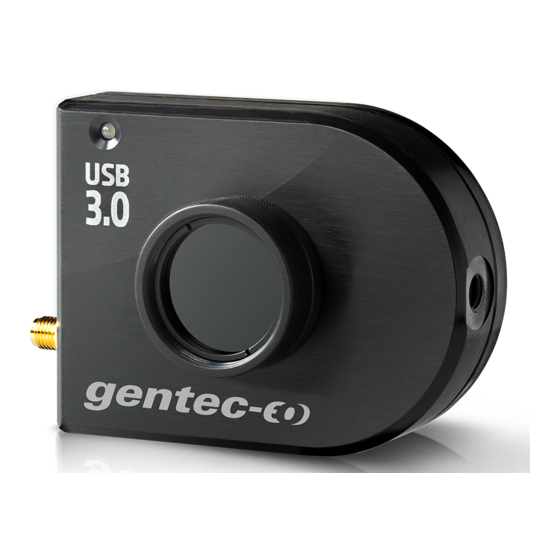
200428 1.2. INTRODUCTION Gentec-EO introduces the Beamage beam profiler series. Its sleek and thin design allows the Beamage to fit between tight optical components. Its USB 3.0 connection and improved algorithm allows very fast frame rates. The Beamage-3.0 2.2 MPixel CMOS sensor has a large ⅔” optical format with a small 5.5 µm pixel pitch allowing high resolution on large beams. -
Page 7: Specifications
Beamage User Manual Revision 23 1.3. SPECIFICATIONS The following specifications are based on a one-year calibration cycle, an operating temperature of 18 to 28°C (64 to 82 F) and a relative humidity not exceeding 80%. Beamage- Beamage- Beamage- Beamage- Beamage-4M- 3.0-IR 4M-IR FOCUS... - Page 8 Beamage User Manual Revision 23 Minimum and Maximum 0.06 to 200 ms Exposure Times SMA connector 1.1 volts to 24 volts, the rise edge response time is 300 ns External Trigger Trigger signal pulse width: min: 300 ns Optional SMA to BNC adaptor (202273) Damage Thresholds Maximum Average 1 W with ND filter...
- Page 9 Beamage User Manual Revision 23 Measured and Displayed Parameters Displays 3D, 2D, XY (crosshair), Beam Tracking, M Curves 4 Sigma (ISO) - ISO-11146-1:2005 FWHM along crosshair (50%) Beam Diameter Definition along crosshair (13.5%) 86% effective diameter (D86) Custom along crosshair (%) Centroid - ISO-11146-1:2005 Beam Center Definition First Encountered Peak...
- Page 10 Disable any power saving settings on your computer; Multi Camera When working with more than one camera, we strongly recommend using one USB3.0 Recommendation port per camera and a recent high end computer for optimal performance Internet Upgrades Downloadable at www.gentec-eo.com/downloads...
-
Page 11: Mechanical Description
Beamage User Manual Revision 23 1.4. MECHANICAL DESCRIPTION Figure 1-1 Beamage series front and side views Aperture The aperture of the Beamage and the screw threads are C-MOUNT, allowing easy connectivity with optical accessories such as attenuation filters, UV converters or lenses. The sensor is centered with the aperture’s center. - Page 12 Beamage User Manual Revision 23 Disable any power saving settings on your computer. It could reduce the power attribution on the USB port and the Beamage camera needs all the power from the USB-3.0 port to provide a stable communication. ...
- Page 13 Beamage User Manual Revision 23 Connector screws: Screw until it is tight, but be careful not to screw too tight. This could potentially damage the connector. Do not shake the cable when the Beamage is connected. Do not apply pressure on the connector when it is connected to a Beamage. ...
-
Page 14: Spectral Curves
Beamage User Manual Revision 23 1.5. SPECTRAL CURVES Figure 1-3 Spectral response of the CMOS sensor Figure 1-4 Transmission of the ND4.0 filter... - Page 15 Beamage User Manual Revision 23 Figure 1-5 Minimum measurable power and saturation power level...
- Page 16 For higher densities please refer to the Beamage Accessories User Manual to correctly attenuate your laser * : Maximum saturation is limited to 10 W/cm² due to the filter’s damage threshold. You can request the sensor’s maximum saturation intensity by contacting Gentec-EO.
-
Page 17: Quick Start Procedure
Beamage User Manual Revision 23 2. QUICK START PROCEDURE Install the PC-Beamage Software. Install the USB Drivers. Make sure to follow the installation instructions (refer to Appendix B). NOTE: The drivers must be reinstalled with each new software installation. If necessary, update the firmware using the BeamageUpdater file (Refer to Appendix C). - Page 18 Beamage User Manual Revision 23 Press Start Capture. Let the Auto Exposure algorithm find the correct exposure time. This should take a few seconds. If the exposure time is 200 ms and your beam is underexposed, you need to remove some attenuation.
-
Page 19: User Interface
Beamage User Manual Revision 23 3. USER INTERFACE Figure 3-1 PC-Beamage user interface Main Controls The top portion of the software is in a ribbon format and includes all the main controls. These are grouped by family, including Capture controls, File controls, Startup Config controls, Buffer controls, Data Computation controls (which include a very useful spatial filter and a normalizing function), M2 controls and Information controls. -
Page 20: Main Controls
Beamage User Manual Revision 23 3.1. MAIN CONTROLS Figure 3-2 Main controls To give more room to the graphical display and less to the ribbon, you can minimize the ribbon by right- clicking on it and choosing “Minimize the ribbon”. You can retrieve the ribbon at any time by right-clicking on the upper portion of the window and unchecking “Minimize the ribbon”. -
Page 21: Capture Controls
Beamage User Manual Revision 23 Figure 3-4 Beamage selector for multiple connected cameras Warning Multiple Beamage beam profilers can be connected to a single computer. However, PC-Beamage does not support multiple cameras at once, so you need to open a new instance of the program for each camera that is connected to your computer. -
Page 22: Capture
Beamage User Manual Revision 23 3.3.2. Capture Figure 3-7 Capture button To start capturing images with the Beamage, click on the “Start Capture”. If no Beamage is connected to the computer or if the “Animate” mode (refer to section 3.4.5) is on, this button will not be available. Once the Beamage starts streaming, the frame rate will be displayed below the button in frames per second (fps). -
Page 23: Subtract Background
Beamage User Manual Revision 23 3.3.3. Subtract Background Figure 3-9 Subtract Background button The “Subtract Background” button includes a drop-down menu in its lower part. The list contains a “Capture” button, a “Load” button, a “Save” button and a “Toggle” button. When you start capturing images while the Subtract Background button is not activated, the diameter measurements under “Measurements”... - Page 24 Beamage User Manual Revision 23 Figure 3-11 “About background subtraction” message Warning It is mandatory to make a background subtraction to comply with ISO- 11146-3:2004 (Section 3). Once you have clicked the upper part of the “Subtract Background” button or the “Capture” button in the drop-down menu, the following message box will appear: Figure 3-12 ”Please block your laser”...
-
Page 25: Buffer Controls
Beamage User Manual Revision 23 Once the background subtraction routine is done, the Subtract Background button turns orange. The beam can then be unblocked to begin a measurement. Figure 3-13 : The Subtract Background button becomes orange once the background noise map is captured The detector background map will be subtracted from all the images that will follow. -
Page 26: Image Index
Beamage User Manual Revision 23 Figure 3-15 Buffer controls Warning Note that all images are stored in the RAM memory of your computer, which could limit the number of images in the buffer. 3.4.1. Image Index Figure 3-16 Image Index The “Image Index”... -
Page 27: Clear Buffer
Beamage User Manual Revision 23 3.4.4. Clear Buffer Figure 3-19 Clear Buffer button The “Clear Buffer” button clears the entire buffer. The captured frames will no longer be available, and any measurements will also be erased. -
Page 28: Animate
Beamage User Manual Revision 23 3.4.5. Animate Figure 3-20 Animate button Once the Beamage has captured frames in its buffer, it is possible to stream them in a playback manner. With as much as 128 frames temporarily saved in the buffer, simply clicking the animation button will create an animation with any display (2D, 3D, and XY). - Page 29 Beamage User Manual Revision 23 Figure 3-24 Available filters The “Filters” button opens a dropdown menu with 3 options. Two spatial filters are available: “Smoothing” and “Despeckle”. These two filters are useful for low-quality lasers or low-level signals. Note that the “Despeckle”...
-
Page 30: Normalize
Beamage User Manual Revision 23 3.5.2. Normalize Figure 3-26 Normalize button The “Normalize” button will spread the graph’s (3D, 2D, and XY) intensity over the full range (0% to 100%). Note that only the displays are normalized, the normalization does not affect the centroid and diameter computations. -
Page 31: File Controls
Beamage User Manual Revision 23 SMA Connector Figure 3-29 SMA Connector for Trigger Input 3.6. FILE CONTROLS The “File Menu” opens and saves frames captured with the Beamage, and also prints a complete report. These controls are not available while capturing images, except for “Start Data Acquisition” function, which is only available while the camera is streaming. -
Page 32: Save All Images In Buffer
Beamage User Manual Revision 23 Click on the “Save Current Image” button to save the currently displayed image. This option will only save 1 frame. Data can be saved in native *.BMG format, in text *.TXT format or in binary *.BIN format. Note that only the *.BMG format can be re-opened with the PC-Beamage software. -
Page 33: Print Report
Beamage User Manual Revision 23 Warning Each *.BMG file can take up to 8.50 MB, each *JPG file can take up to 200KB and each *.BMP file can take up to 1.2 MB on the hard drive. Acquiring multiple frames can quickly sum up to multiple GB of data. Fast acquisition should only be done on the computer’s hard drive and cannot be done on an external drive or on a server hard drive. - Page 34 Beamage User Manual Revision 23 After choosing the default or the custom report, a print preview will appear in the PC-Beamage software. To print the report, click “Print”. To exit without printing, click “Exit”. These buttons are located on the right-hand side.
- Page 35 Beamage User Manual Revision 23 Figure 3-38 Default Print Report Page 1...
- Page 36 Beamage User Manual Revision 23 The second page prints the cross-sectional XY graphs along the crosshairs. If the “Cursor”, the “Gaussian Fit”, “FWHM”, or the “1/e ” options are selected (refer to section 0), they will also appear in the report. Figure 3-39 Default Print Report Page 2...
-
Page 37: Startup Config Controls
Beamage User Manual Revision 23 3.7. STARTUP CONFIG CONTROLS The PC-Beamage software can load, save and reset to the default factory state the software settings. The file extension is *.geo. Figure 3-40 Startup Config Controls When closing the PC-Beamage, all current settings will be saved and will automatically be loaded next time the PC-Beamage is opened. -
Page 38: Divergence
Beamage User Manual Revision 23 3.8.2. Divergence Figure 3-43 Divergence Button The “Divergence” button activates a new tab on the right-hand side of the user interface. It contains all the settings and results relative to the beam divergence (refer to section 4.4). To compute the divergence and abide by the ISO-11146-1:2005 standard, the first step is to place an aberration-free lens between the Beamage and the laser. -
Page 39: Fixed Crosshair
Beamage User Manual Revision 23 3.8.5. Fixed Crosshair Figure 3-46 Fixed Crosshair Panel The “Fixed Crosshair Panel” panel activates a new tab on the right-hand side of the user interface. It contains the settings relative to the fixed crosshair. This tool allows you to easily fix and see the crosshair at a precise position on the sensor, and also to adjust the crosshair’s orientation. -
Page 40: Beamage-M2 Mode
Beamage User Manual Revision 23 3.9. BEAMAGE-M2 MODE Figure 3-49 Show/Hide M² Mode Tabs The M2 mode activates the M measurement functions of PC-Beamage software. The M factor can be considered as a quantitative indicator of laser beam quality. In terms of propagation, it is an indicator of closeness to an ideal Gaussian beam at the same wavelength. -
Page 41: Contact Support
3.11.2. Contact Support Figure 3-54 Contact Support Button If you need support or help with your PC-Beamage software you can contact a Gentec-EO representative by clicking on the Contact Support button. By clicking on this button, a Contact Support panel will appear... -
Page 42: About
Beamage setup and your beam profiler. You can also attach any files, images, or documents concerning your issue to this email. 3.11.3. About Figure 3-56 About Button To learn more about the PC-Beamage software, camera and sensor, click the “About” Button. You can also obtain the latest PC-Beamage software version on our website at www.gentec-eo.com/downloads... -
Page 43: Help
3.11.4. Help Figure 3-57 Help Button The “Help” button opens the Beamage Series user manual. All information, tips, warnings and troubleshooting about the software are in this manual. It is also possible to open both the Beamage user manual, Beamage M² User Manual and the Beamage accessories user manual. -
Page 44: Home And Setup Panels
Beamage User Manual Revision 23 4. HOME AND SETUP PANELS The PC-Beamage offers different panels to view the measurements and set different options for the Beamage. Home: Controls the computation parameters and displays the beam’s diameter and centroid information. Setup: Controls the Beamage parameters. Data Acquisition: Controls the acquisition parameters Divergence: Controls the divergence parameters and displays the results. -
Page 45: Home
Beamage User Manual Revision 23 4.1. HOME Figure 4-2 Home Tab Main Controls: Defines the beam width definition and crosshair position. Diameter: Displays the beam diameter computation results. Centroid: Displays the beam’s centroid and peak coordinates. -
Page 46: Main Controls
Beamage User Manual Revision 23 4.1.1. Main Controls The “Main Controls” section allows the user to set the desired beam diameter definition and crosshair position. Use the drop-down menu to select the desired settings. 4.1.1.1. Beam Diameter Definition By default, the beam width definition is set to “4 sigma (ISO)” which respects the ISO-11146-1:2005 and ISO11146-2:2005 standards (refer to Appendix A. - Page 47 Beamage User Manual Revision 23 4.1.2.1. Diameter The beam diameter “dσx” and “dσy” refers to the beam width closest to the x horizontal axis and y vertical axis as defined by the ISO-11146-1:2005 and ISO11146-2:2005 standards. If the Beam Diameter Definition is set to “FWHM along crosshair”...
- Page 48 Beamage User Manual Revision 23 The beam “Centroid” corresponds to the beam’s first order distribution as defined by the ISO-11146- 1:2005 and ISO-11146-2:2005 standards (refer to Appendix A) The beam’s “Peak” position corresponds to the pixel’s peak value position. If many pixels correspond to the peak value, the crosshair will be centered on the first peak.
-
Page 49: Setup
Beamage User Manual Revision 23 4.2. SETUP The “Setup” tab allows the user to set the Beamage parameters. Figure 4-6 Setup Tab Exposure time: Controls the Beamage sensor’s exposure time. Image orientation: Rotates or flips the captured image. Image Averaging: Applies a temporal filter by averaging multiple frames Active Area: Selects the region of interest. -
Page 50: Exposure Time
Beamage User Manual Revision 23 4.2.1. Exposure Time The “Exposure Time” controls the Beamage’s exposure time settings. It can be set from 0.06 ms to 200 ms. The “Auto” option will automatically set the exposure time in order to have the maximum beam intensity at 85% of the sensor’s saturation level. -
Page 51: Image Averaging
Beamage User Manual Revision 23 4.2.3. Image Averaging The “Image Averaging” function is a temporal filter that captures a specified number of frames (2, 5, or 10) and averages the frames pixel by pixel to create a single time-averaged image. This lowers the total frame rate because multiple frames need to be captured for one computation. -
Page 52: Gain
Beamage User Manual Revision 23 When working with large beams, optimize the speed of the data transfer by reducing the spatial resolution using the Pixel Addressing function. 4.2.6. Gain The “Gain” setting allows the user to set a numerical gain on the captured image. The gain must be between 1 and 10. -
Page 53: Data Acquisition
Beamage User Manual Revision 23 It is possible to manually set a value for the PMF. Simply enter the desired value in the white box and press enter. The beam dimensions will be adjusted accordingly. If a camera lens is used with the Beamage camera, it is possible to follow the camera lens calibration steps by clicking on the “Calibrate”... - Page 54 Beamage User Manual Revision 23 Figure 4-11 Data Acquisition Tab...
-
Page 55: Divergence
Beamage User Manual Revision 23 The “Duration” defines the time for which the acquisition will keep running. The countdown starts as soon as the user presses the “Start Data Acquisition” button located in the “Main Controls”. The user can select the number of days, hours, minutes and seconds. - Page 56 Beamage User Manual Revision 23 Figure 4-12 Divergence Tab Warning The Beamage sensor must be placed precisely at the focal point, not at the beam waist.
-
Page 57: Relative Position
Beamage User Manual Revision 23 4.5. RELATIVE POSITION 4.5.1. Setup The “Setup” section, which displays the coordinate system of the Beamage sensor on the right side, allows the user to select the parameter that will be considered as the origin position (0,0) by the software. Figure 4-13 Relative Position Tab By selecting “Centroid”... -
Page 58: Measurements
Beamage User Manual Revision 23 point, the coordinate values for both X and Y axes will automatically be set beside “User-defined” in the “Relative Position” tab. Figure 4-14 Coordinates Defined by User To set the origin back to its default position (0,0), click on the “Reset origin” button below “User-defined”. This will also automatically select the default option “Centroid”... -
Page 59: Camera Lens
Beamage User Manual Revision 23 4.6. CAMERA LENS Prior to profiling a beam with a camera lens, one must adjust the Pixel Multiplication Factor of the lens (see section 5.2.8). The “Camera lens calibration” section allows the user to calibrate the PC-Beamage software when a camera lens is used with the Beamage. -
Page 60: Fixed Crosshair
Beamage User Manual Revision 23 4. Enter this distance (in mm) in the appropriate box and press enter. 5. Finally, click on the “Calibrate” button to automatically set the Pixel Multiplication Factor (PMF) value found in the bottom of the “Setup” tab. Once the PMF is set, the beam dimensions will be adjusted to compensate for the magnification of the camera lens (Beam Tracking Display). - Page 61 Beamage User Manual Revision 23 Figure 4-20 Fixed Crosshair Section By selecting “Centroid” and clicking “Set now”, the user chooses to position the origin of the crosshairs at the calculated centroid position (center of energy). By selecting “Peak” and clicking “Set now”, the user chooses to position the origin of the crosshairs at the calculated peak energy position (highest measured value).
- Page 62 Beamage User Manual Revision 23 Figure 4-22 Fixed Crosshairs at Peak Position in the 2D Display Figure 4-23 Fixed Crosshairs at Peak Position in the Crosshair Display It is also possible to set the origin in the 2D display. When the Fixed option is active in the “Home” panel, the picker tool will be activated in the 2D Display.
- Page 63 Beamage User Manual Revision 23 Figure 4-24 Fixed Crosshairs picker tool in the 2D Display Figure 4-25 Fixed Crosshairs picking position in the 2D Display...
-
Page 64: Orientation Setup
Beamage User Manual Revision 23 4.7.2. Orientation Setup To activate the fixed crosshair orientation option, go to the “Home” panel, in the “Main Controls” section and choose the Fixed option for the crosshair orientation. This will automatically open the “Fixed Crosshair”... -
Page 65: Display Panel
Beamage User Manual Revision 23 5. DISPLAY PANEL PC-Beamage offers four different display modes to view and analyze the laser beam. 3D Display: A real time display of the beam intensity in a 3D representation. 2D Display: A real time display of the beam intensity in a 2D representation. Crosshair Display: A real time display of the beam’s shape along the crosshairs. -
Page 66: Display: Controls
Beamage User Manual Revision 23 x axis Y axis Figure 5-2 3D Display 5.1.1. 3D Display: Controls The toolbar buttons on the upper right corner control the 3D image. Print Screen: Saves a *.BMP or *.JPG image of the current 3D display. Reset View: Resets the display to its original parameters. -
Page 67: Display
Beamage User Manual Revision 23 5.2. 2D DISPLAY The 2D Display represents the beam’s intensity in two dimensions. False coloring is added to increase the contrast. The color legend used for the various intensity levels is available in the “Main Controls” ribbon (refer to section 3.11.1). -
Page 68: Keyboard Controls
Beamage User Manual Revision 23 Keyboard Controls: The position and the zoom level of the 2D • CTRL Zoom in : • CTRL Zoom out : ← CTRL • Left translation : • Right translation : → CTRL ↑ CTRL •... -
Page 69: Crosshair Display
Beamage User Manual Revision 23 5.3. CROSSHAIR DISPLAY The “Crosshair Display” plots cross-sectional graphs of the beam along the crosshairs. The crosshairs position and orientation are defined in the “Home” tab (refer to section 4.1.1.2) Figure 5-5 Crosshair Display 5.3.1. Crosshair Display: Controls The toolbar buttons on the upper right corner control the crosshair graphs. -
Page 70: Gaussian Fit
Beamage User Manual Revision 23 5.3.2. Gaussian Fit The “Gaussian Fit” function fits the best Gaussian curve on the experimental data. When the “Gaussian Fit” is activated, the following pieces of information are displayed in the upper right part of the graph. 5.3.2.1. -
Page 71: Beam Tracking Display
Beamage User Manual Revision 23 5.4. BEAM TRACKING DISPLAY The “Beam Tracking Display” shows the variation of the position of the centroid on the sensor. The yellow cross represents the last calculated centroid position while the blue dots represent the previous ones. A dot is added to the chart at each computation. -
Page 72: Beam Tracking Display: Controls
Beamage User Manual Revision 23 The beam positional stability values are based on the standard deviation concept . Small values represent small deviations and a good stability. For tracking more than 2000 points, please refer and use the acquisition feature: 3.6.4 Start Data Acquisition. -
Page 73: Mmode 2 Mmodeode
Beamage User Manual Revision 23 6. M MODE The M factor can be considered as a quantitative indicator of laser beam quality. In terms of propagation, it is an indicator of closeness to an ideal Gaussian beam at the same wavelength. Please refer to Appendix B for the theory about M quality factor. -
Page 74: Third Party Commands
Labview VIs using the LabVIEW commands. Gentec-EO also offers .Net named pipes commands to allow you to create your own C++, C# or Visual Basic application. Named pipes can be used to provide communication between processes on the same computer or between processes on different computers across a network. - Page 75 Beamage User Manual Revision 23 Available Available VI commands for Description samples LabVIEW and .Net Connection Commands Checks to ensure the required DLL file is present in Verify DLL the directory in which the LabVIEW VIs are located. Connects to the LabVIEW pipeline opened by the Connect to PC PC-Beamage software.
- Page 76 Save As Current Image control in the software. Image format will be *.TXT. Save the current 2D display image into *CTLBMPSAVE MyDocuments/Gentec-eo/beamage.bmp. Measurement Commands The measurement for the Diameter and Position. Running the selected commands returns the reading from the software.
- Page 77 Beamage User Manual Revision 23 Returns the X roughness fit measurement Measure X Roughness *MEARFITX returns the Y roughness fit measurement *MEARFITY Measure Y Roughness Returns the X or Y graph’s intensity level at cursor *MEAPERX position in % *MEAPERY - Returns the X or Y graph’s cursor position *MEAPOSX *MEAPOSY...
- Page 78 Beamage User Manual Revision 23 Running this has the same effect as pressing the Activate 1OVRE. *ACTXYE2 1/e2 button in the Crosshair Display. Running this has the same effect as pressing the Activate Background *ACTBACK Subtract background in the ribbon. Running this has the same effect as pressing the Deactivate Background *DACTBACK...
-
Page 79: Labview Example
Beamage User Manual Revision 23 7.2. LABVIEW EXAMPLE The VIs have all been used to create an example software. The front panel of this example is shown below. Figure 7-1 Beamage LabVIEW Example The example is written to be easy to use and understand so as to aid in the development of custom LabVIEW software. - Page 80 Beamage User Manual Revision 23 4. Plug a Beamage Camera into a USB port on the PC in use. Start PC-Beamage and let it connect to the camera. 5. Under the Show/Hide Options menu item, select Start LabVIEW Pipeline. The PC-Beamage software will verify the connection.
-
Page 81: Net Example
7.3. .NET EXAMPLE The NamedPipeClient.sln solution is a C++ standalone application to show how to use the PC- Beamage’s .Net commands supplied by Gentec-EO. Figure 7-2 Beamage C++ Standalone Example The example is written to be easy to use and understand so as to aid in the development of custom... - Page 82 Beamage User Manual Revision 23 1. Compile and run the NamedPipeClient.sln. 2. Plug a Beamage Camera into a USB port on the PC in use. Start PC-Beamage and let it connect to the camera. 3. Under the Show/Hide Options menu item, select Start .Net Pipeline. The PC-Beamage software will verify the connection.
-
Page 83: Beamage Sdk
Beamage camera to their system without using Gentec-EO’s PC-Beamage software. This is for experienced programmers only. Gentec-EO’s Beamage SDK is a dll (Dynamic Link Library) that communicates with the camera drivers. It provides our customers with specific software functions to control the Beamage camera and retrieve images from it, in order to build custom Windows applications. -
Page 84: Troubleshooting And Tips
Beamage User Manual Revision 23 9. TROUBLESHOOTING AND TIPS 1) While trying to install PC-Beamage, it is possible that the installation of Microsoft Visual C++ 2015-2019 Redistributable (x86) is required. Beamage Installer will do this installation for you, but if this is not possible, an error message will be displayed when PC-Beamage starts, Figure 9-1 Missing DLL file Error Message You can try an alternative installation of PC-Beamage and the missing dll file, to do this, please follow... - Page 85 Beamage User Manual Revision 23 Warning Make sure you do not have another version of PC-Beamage installed on your computer, see Figure 9-3, and if so, please uninstall it before using the keyboard shortcut. Figure 9-3 Other Version Found Message 3) Wait for the PC-Beamage installation to complete.
- Page 86 Beamage.exe instance running. If more than one are running, end all processes and open PC- Beamage again. • If the problem persists, please disconnect the Beamage and connect it again. • If the problem persists, please contact your Gentec-EO representative or contact us at service@gentec-eo.com. 8) The detected serial number is 000000...
- Page 87 3.0 is damaged and unusable. In that case, we strongly recommend not using this USB-3.0 with the Beamage camera, it could have a negative impact on the communication stability. For more information, please contact your Gentec-EO representative or contact us at service@gentec- eo.com.
-
Page 88: Declaration Of Conformity
Beamage User Manual Revision 23 10. DECLARATION OF CONFORMITY Application of Council Directive(s): 2014/30/EU The EMC Directive Manufacturer’s Name: Gentec Electro Optics, Inc. Manufacturer’s Address: 445 St-Jean Baptiste, suite 160 (Québec), Canada G2E 5N7 European Representative’s Name: Laser Components S.A.S. Representative’s Address: 45 bis Route des Gardes 92190 Meudon (France) -
Page 89: Ukca Declaration Of Conformity
Beamage User Manual Revision 23 11. UKCA DECLARATION OF CONFORMITY Application of Council Directive(s): 2014/30/EU The EMC Directive Manufacturer’s Name: Gentec Electro Optics, Inc. Manufacturer’s Address: 445 St-Jean Baptiste, suite 160 (Québec), Canada G2E 5N7 European Representative’s Name: Laser Components S.A.S. Representative’s Address: 45 bis Route des Gardes 92190 Meudon (France) -
Page 90: Appendix A. Iso11146 And Iso11670 Definitions
Beamage User Manual Revision 23 APPENDIX A. ISO11146 AND ISO11670 DEFINITIONS The beam centroid coordinates are given by: ∞ ∞ �� ( ��, ��, �� ) ���������� ∫ ∫ −∞ −∞ ��̅ ( �� ) = ∞ ∞ �� ( ��, ��, �� ) �������� ∫... - Page 91 Beamage User Manual Revision 23 �� �� �� �� �� �� �� �� �� �� �� In the laboratory or usual system of coordinates (X’,Y’,Z’), the coordinates of the latest calculated position of the centroid for both X’ and Y’ axes are given by the following equations: ∞...
- Page 92 Beamage User Manual Revision 23 ( z ) = 4s Δ Δ ( z ) = 4s The overall positional stability is given by: Δ ( �� ) = 2√2�� In the previous 3 equations, the standard deviations are defined by the following equations: ∑...
-
Page 93: Appendix B. M 2 Quality Factor Theory
Beamage User Manual Revision 23 APPENDIX B. M QUALITY FACTOR THEORY Understanding the M Factor The M factor, which is unitless, can be considered as a quantitative indicator of laser beam quality. It indicates the deviation of the measured beam from a theoretical Gaussian beam of the same wavelength. It can mathematically be defined as the ratio between the Beam Parameter Product (BPP = beam waist radius (w ) multiplied by divergence half-angle (θ)) of the measured beam with the theoretical Gaussian... - Page 94 Beamage User Manual Revision 23 Mathematically, it is given by the following equation: ��( �� ��ℎ �� �� ��ℎ �� Far from the beam waist, the beam expansion becomes linear and the theoretical divergence half-angle θ (half of the angle shown in the Beam Propagation Diagram) can be obtained by evaluating the limit of the beam radius’...
-
Page 95: Practical Measurement
Beamage User Manual Revision 23 ( �� ) = �� �� √ 1 + �� /�� ������ �� ������ ������ The M factor affects both beam waist radius and Rayleigh length, according to the following equations : ���� ��ℎ �� ��... -
Page 96: Appendix C. The Pc-Beamage Software
Beamage User Manual Revision 23 APPENDIX C. THE PC-BEAMAGE SOFTWARE 1) Download and run the Beamage Installer. The latest version can be downloaded from the Downloads bottom following page: https://www.gentec- eo.com/resources/download-center 2) Use the installer to install the PC-Beamage Software, see Figure C-1. Figure C-1 Beamage Installer system, you can click on the “Install All”... - Page 97 Beamage User Manual Revision 23 Figure C-2 Install All Button...
-
Page 98: Appendix D. Beamage-3.0 Driver Installation Quick Guide
1) The latest available version of PC-Beamage must be installed before setting the drivers. It can be downloaded from the following web page: https://www.gentec-eo.com/resources/download-center 2) If the software is already installed on your computer, please make sure it is the latest available version of PC-Beamage. - Page 99 Beamage User Manual Revision 23 Figure D-2 Beamage Installer (Beamage-3.0 Driver) 4) Click on the “Drivers” button and wait the driver installation done, see Figure D-3 Figure D-3 Camera Drivers When installing the drivers, it is possible that the installation of Microsoft Visual C++ 2015-2019 Redistributable is required.
- Page 100 Beamage User Manual Revision 23 Figure D-4 Missing DLL file Error Message You can download the missing dll file using the link below: 32 bits: Microsoft Visual C++ 2015-2019 (x86) 64 bits: Microsoft Visual C++ 2015-2019 (x64) Or by visiting the Microsoft website, Visual Studio 2015, 2017 and 2019 section: Support Microsoft Verify that the driver has been correctly installed It is not necessary to follow these steps to install the USB drivers.
- Page 101 Beamage User Manual Revision 23 Figure D-6 Cypress USB BootLoader 3) Open PC-Beamage and make sure Cypress USB BootLoader has been replaced by Cypress USB BulkloopExample. Figure D-7 Cypress USB BulkloopExample...
-
Page 102: Appendix E. Beamage Firmware Installation Quick Guide
If so, it is important to update the firmware version and to reinstall the drivers in order to use the PC-Beamage’s new functions. 2) First, download the latest Beamage Installer available on Gentec-EO’s website at https://www.gentec-eo.com/resources/download-center Erreur ! Référence de lien hypertexte... - Page 103 Beamage User Manual Revision 23 The Beamage-3.0 Updater might ask you to reset the Beamage. If so, please disconnect and reconnect the Beamage and click on “Update” again. 6) Once this is done, a message box will appear. Click on OK. Figure E-3 Update Complete 7) Once the firmware is up to date, update the drivers by following the steps described in Appendix B.
-
Page 104: Appendix F. Check The Update Of Pc-Beamage
Beamage User Manual Revision 23 APPENDIX F. CHECK THE UPDATE OF PC-BEAMAGE 1) If the new version of PC-Beamage is available, the following message will be displayed when PC- Beamage is started, see Figure F-1 Figure F-1 Update Message 2) Click on the “Yes” button to start the download of Beamage Installer. The Beamage Installer contains the new version of PC-Beamage, see Figure F-2 Figure F-2 PC-Beamage Update 3) Once the Beamage Installer is downloaded, PC-Beamage will close and the new Beamage... - Page 105 Beamage User Manual Revision 23 Figure F-3 PC-Beamage Install Button To stop being notified about new updates, select the “Don’t show this window again” option and click the “No” button to close the message, see Figure F-4 Figure F-4 Don't show this window again option...
- Page 106 Beamage User Manual Revision 23 Checking for a new version of PC-Beamage without an internet connection If your computer doesn’t have an internet connection, a message will be displayed every 6 months after installation date, this message invites visit website https://www.gentec- eo.com/fr/ressources/telechargements and check if there is a new software version of PC-Beamage, see...
-
Page 107: Appendix G. Recycling And Separation Procedure For Weee
Beamage User Manual Revision 23 APPENDIX G. RECYCLING AND SEPARATION PROCEDURE FOR WEEE This section is used by the recycling center when the Beamage reaches its end of line. Breaking the calibration seal or opening the Beamage’s case will void the warranty The complete Beamage contains: 1 Beamage 1 USB 3.0 cable with screw locks... -
Page 108: Appendix H. Complete List Of Saved Settings
Beamage User Manual Revision 23 APPENDIX H. COMPLETE LIST OF SAVED SETTINGS • • Image buffer size Acquisition tab options: • Acquisition mode Smoothing filter activated • Duration: Despeckle filter activated ▪ • Days IR filter activated ▪ • Hours Normalize option activated ▪... -
Page 109: Appendix I. Saturation Limit For Beamage With Nd4.0 Filter
Beamage User Manual Revision 23 APPENDIX I. SATURATION LIMIT FOR BEAMAGE WITH ND4.0 FILTER Figure H-1 Saturation Limit for Beamage with ND4.0 Filter and 0.06 msec Exposure Time... - Page 110 Beamage User Manual Revision 23...
Need help?
Do you have a question about the Beamage Series and is the answer not in the manual?
Questions and answers