Table of Contents
Advertisement
Quick Links
Advertisement
Table of Contents

Subscribe to Our Youtube Channel
Related Manuals for Global SV 550

Summary of Contents for Global SV 550
- Page 1 Operating manual SV 550 110824...
- Page 2 Contents Chapter Safety instruction Product Introduction 2.1 Overview 2.2 Components 2.3 Specifications 2.4 Applications Installation 3.1 Installation of Motor Module 3.2 Installation of Control box 3.3 Installation of Pedal 3.4 Connection of System Power 3.5 Setting the needle positions (only with synchro) Parameter setting and reset 4.1 Operator level P 4.2 Technician level F...
-
Page 3: Safety Instruction
1. Safety Instruction Caution Please read the operating instruction of this product carefully before operating this product. Our products are applicable to stated sewing equipments only, don’t use them for other applications. Please read the operating instruction carefully before installing and adjusting the product This product should be installed and operated by professionally trained personal only It is users forbidden to change any part of the controller, users take all consequences caused by the change themselves... -
Page 4: Product Introduction
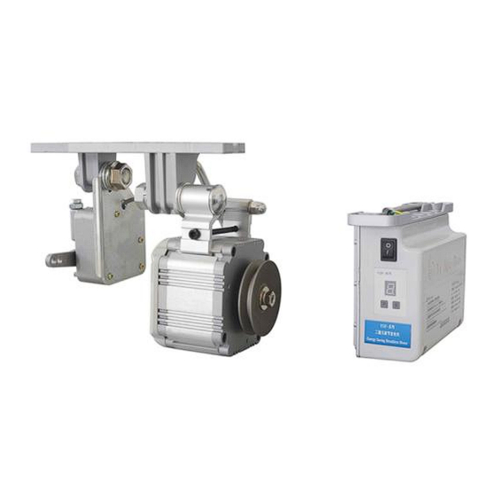
2. Product Introduction Overview The SV-550, energy saving industrial sewing machine brushless motor has many advantages compared to the traditional clutch motor: low friction, low noise and vibration level, low temperature rise, longer working life, smaller dimensions and lighter in weight. But what’s most important, SV-550 can save about 71% energy compared to clutch motors and can be used widely on various industrial sewing machines to replace the clutch motor perfectly. - Page 5 ≤ 0,3 sec. Carton size Gross weight per carton Applications SV 550 motor can be used for light and medium weight single needle lockstitch machine, light weight double needle lockstitch machine and heavy duty overlock and interlock sewing machines. 110824...
-
Page 6: Installation
3. Installation 3.1 Installation of Motor Module A: Fix the three bracket screws into the reserved holes on the table of the sewing machine, then fix the motor under the table by the motor bracket. Adjust the position of the motor bracket so the motor pulley and the machine pulley are aligned properly. - Page 7 3.3 Installation of Pedal Correct mounting of the pedal rod is in a vertical position between pedal and speed control unit. Adjust the angle of the pedal to a 15 degree angle between pedal and the ground. 15 ° 3.4 Connection of system power Connect the power cord of the control box to a 220 Volt single phase power supply with separate earth device.
- Page 8 3.5 Setting the needle positions If the motor is used without synchronizer (parameter M = 0), this step can be ignored. Needle DOWN position: 1. Rotate the handwheel until the needle is in the Needle DOWN position 2. Rotate the Needle DOWN disk (see picture 2) in the correct direction until the gap in the disc is equal to the photo sensor (see picture 3 and 4) Needle UP position: 1.
-
Page 9: Parameter Setting
4. Parameter setting Normal mode P: if the dot is shown in the display this means lockstitch rotation direction, no dot means chainstitch rotation direction. On the SV 550 there are 2 parameter levels: 1. operator level P 2. technician level F Operator level P: In normal mode (P.) press the P button to select a parameter... - Page 10 Technician level F: To enter the technician level, in normal mode, first press the S button and then also press the P button for 3 seconds until the display shows “F”. Display will now show the technician level F. Press P button to select a parameter in the technician level F: M = synchronizer mode (0 = no synchro, 1 = synchro) Z = speed level setting (see columns next page) L = speed limit setting (see columns next page)
- Page 11 Max Speed Setting: 1. With Z=0, below is the speed range (RPM) under different settings of parameter L: Max. 1500 2000 2500 3000 3500 4000 4500 5000 5500 6000 speed For example, set Z=0 and L=8, the speed range is between 0-5500 RPM (adjustable by parameter V in the operator parameter level) 2.
-
Page 12: Environment Requirements
5. Environment Requirements 1. Keep the motor and control box away from high magnetic field environments and radiation environments to avoid malfunction. 2. The work environment temperature must be in the range of 5 – 45 °C. 3. Don’t use this product next to heat sources (such as radiator). 4. - Page 13 Fault 5: The motor keeps running by itself when the power is turned ON. Check if parameter M is set correctly. When parameter M is set to 1 but NO synchro is used the motor will start to run automatically when the power is turned ON. For use WITHOUT synchro parameter M must be set to 0.
-
Page 14: Additional Remarks
Fault 8: The display shows “E3” Turn OFF the power of the control box, wait 10 seconds and turn the power back ON. Fault 9: The fuse is blown as soon as the power of the control box is turned ON. If the problem can not be solved by replacing the fuse contact your distributor.
Need help?
Do you have a question about the SV 550 and is the answer not in the manual?
Questions and answers