Table of Contents
Advertisement
Quick Links
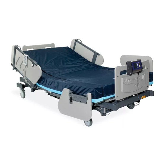
Burke Tri -Flex II Air Mattress
™
OPERATING INSTRUCTIONS
OPERATING INSTRUCTIONS MANUAL
Burke Low Air Loss Support System Alternating
Pressure System With Width Expansion
Using Real Time Pressure Monitoring (RTPM) Sensor Technology
US & INTERNATIONAL PATENTS PENDING
An FDA Registered Company, Products are FDA listed.
1800 Merriam Lane
Kansas City, KS 66106
1-913-722-5658
Email: burkebariatric@burkebariatric.com
www.burkebariatric.com
MADE IN USA
Advertisement
Table of Contents

Related Manuals for Burke Tri-Flex II


Summary of Contents for Burke Tri-Flex II
- Page 1 Burke Tri -Flex II Air Mattress ™ OPERATING INSTRUCTIONS OPERATING INSTRUCTIONS MANUAL Burke Low Air Loss Support System Alternating Pressure System With Width Expansion Using Real Time Pressure Monitoring (RTPM) Sensor Technology US & INTERNATIONAL PATENTS PENDING An FDA Registered Company, Products are FDA listed.
- Page 2 Burke, Inc. 1800 Merriam Lane Kansas City, KS 66106 USA www.burkebariatric.com 1-913-722-5658 pn 63568 rev 0117...
-
Page 3: Table Of Contents
TABLE OF CONTENTS SECTION PAGE Danger, Caution and Warning Manufacturer’s Liability Explanation of Symbols Used Control Unit Features Support Surface Features Technical Specifications Safety Instructions Quick Reference Guide Quick Operating Instructions System Set-Up & System Diagram Control Unit Set-Up Operating Instructions CPR Function Patient Transportation Cleaning Procedure... -
Page 4: Danger, Caution And Warning
BURKE INC., or whenever the control unit and mattress system has been used according to the following oper- ating instructions. -
Page 5: Explanation Of Symbols Used
EXPLANATION OF SYMBOLS USED ON THIS DEVICE SYMBOL EXPLANATION POWER Turns unit On/ Off Up or Down key adjusts patient comfort pressure levels. SOFT FIRM Max Inflate Low Air Loss MODE Inflates mattress rapidly (30 minute timer) Inflate Low-Air-Loss Supplies air into the low air loss section of the Low Air Loss MODE... -
Page 6: Control Unit Features
Burke Low Air Loss Support System (Figure -1 Page 14): The Burke Low Air Loss Support System is an alternating pressure & on-demand low air loss system with width expansion side air bolsters, used to provide pressure reduction. It consists of a control unit (A) which is used to inflate a mattress replacement system (B) with width expansion side air bolsters on each side. -
Page 7: Support Surface Features
SUPPORT SURFACE (B) Figure - 1 page 14 • Self contained mattress replacement system (B) with easily detachable components for cleaning. • Detachable urethane coated, 70 Denier nylon taffeta, flame retardant / water repellent, mildew resistant, low friction and low shear, 5” (13cm) high (inflated) detachable lateral tubular air cushions (T) (pg.20). -
Page 8: Technical Specifications
TECHNICAL SPECIFICATIONS ELECTRICAL SPECIFICATIONS U.S. INTL. Input Voltage AC: 120V 220 / 240V Input Frequency: 60 Hz 50 Hz Current: 0.5 A Maximum Power Consumption: 40 +/- 5 W 40 +/- 5 W Circuit Protection: Single/Dual fused, 250V, 1A fast blow fuses. Mode of Operation: Continuous Continuous... - Page 9 Support Surface (B): Air Cushions and Side Bolsters: 70 denier urethane coated nylon, R.F. welded, liquid proof and washable. Pass Cal.117. Base: 1000 denier cordura, liquid proof and washable. Top Sheet: 70 denier urethane coated nylon, low friction, low shear force producing, breathable, liquid resistant and highly vapor permeable.
- Page 10 SAFETY AGENCY APPROVALS ETL Listed: To standard for safety of Medical Electrical Equipment Conforms To: UL STD 60601-1 with respect to Electrical Shock, Fire and Mechanical Hazards Flame Resistance: Unit components meet UL 94V-0. Mattress components pass Standard for California117. FDA REGISTRATION The Manufacturer is an FDA registered company as a manufacturer and as a contract manufacturer whose quality system meets the requirements of FDA 21 CFR, PART...
-
Page 11: Safety Instructions
• Smoking by the patient or anyone else around or on the Burke Low Air Loss Sup- port System is prohibited. Burke Low Air Loss Support System uses room air for circulation through the mattress, smoking will contaminate the system. - Page 12 When opening the large system box or the small Control Unit box, care should be taken such that object used to open the box does not penetrate the box and damage the components inside. Components Supplied: Burke Low Air Loss Support System Box 1 Control Unit Box 1 Mattress Control Unit Box...
-
Page 13: Quick Reference Guide
Pages 18, 19, & 20 THIS SECTION IS FOR QUICK REFERENCE ONLY, PLEASE READ THE ENTIRE MANUAL BEFORE OPERATING THE Burke Low Air Loss Support System SYSTEM DISPLAY PANEL (G): Displays all of the product functions. POWER SWITCH (PS): Press power switch to turn ON or OFF the unit. Amber Light On = Main Power is On but Control Unit is Off, Green Light On = Control Unit is operating. - Page 14 COMFORT CONTROL (CC): 10 LED’s displays the patient comfort pressure levels from 0 to 9. It also provides a guide to the care giver to set approximate comfort pressure level as measured in Parts per Millimeter of Mercury (mmHg), depending on the patient weight. LOCK (LO): Lock out key completely locks the control panel including power switch.
-
Page 15: Quick Operating Instructions
• QUICK OPERATING INSTRUCTIONS • 1. Unroll the Burke Low Air Loss Support System mattress and place it on the bed frame and attach it firmly with straps. Hang the Burke Low Air Loss Support System control unit on the footboard and make sure that the mattress hose assembly is connected securely to the control unit. -
Page 16: System Set-Up & System Diagram
SYSTEM SET-UP Figure –1 PLEASE NOTE: Burke Low Air Loss Support System ALTERNATING PRESSURE System must be installed on bed frames that are equipped with side rails. Please raise side rails on the bed and lock them in position after the patient is on the mattress. - Page 17 CONTROL UNIT RIGHT SIDE 1. Before using the Burke Low Air Loss Support Sys- tem ALTERNATING PRESSURE mattress replace- ment system remove any non Burke Low Air Loss Support System mattress system from the bed frame (BF). 2. Burke Low Air Loss Support System Mattress...
-
Page 18: Operating Instructions
6. Uncoil the power cord (Q) and plug the cord into the appropriate AC power source (X), which is properly grounded. Plug the other end of the power cord into the control unit and press it in place. Care should be taken such that the power cord of the control unit is not pinched, or has any objects placed on it, and also ensure it is not located where it can be stepped on or tripped over. - Page 19 INITIAL POWER UP 2. During initial power up (when power cord (Q) is plugged into the power source), the con- trol unit (A) will be in “STAND BY” with the amber LED on. 3. If the unit is in stand by mode with amber LED on, press the power key and the green LED will turn on.
- Page 20 PATIENT COMFORT CONTROL LEVEL (CC) The Burke Low Air Loss Support System is designed for patients weighting between 50 1000 lbs. (22 Kg. 455 Kg.). Pressing the comfort control buttons increases or decreas- es the pressure. a. Pressing the SOFT key (K) towards the LED 0 position reduces the pressure setting, pressing the FIRM key (K) towards the LED 9 position increases the pressure.
- Page 21 ON- DEMAND LOW AIR LOSS Low Air Loss MODE To activate Low Air Loss mode (AL) please press (FN) key. The Low Inflate Air Loss (AL) LED will light up. In this mode the patient will receive low air loss relief. This mattress contains a Low Air Loss Top Sheet;...
- Page 22 The advantage of the mattress is that the patient need never be disturbed in order to move for tests or other procedures. The patient may remain in position and the side bolsters can be deflated in order to narrow the width of the Burke Bed to fit through doors. To narrow the bed Make sure the switch marked “Width Expansion”...
-
Page 23: Cpr Function
CPR FUNCTION 1. To deflate the mattress / overlay pad or for a CPR procedure, press the quick release but- tons on both the coupling bodies (R), and simultaneously pull the single piece hose connec- tor (V) from the control unit flange connector. Also disconnect the side bolster deflate insert connector from the bolster hose body connector present on the bottom right corner of the mattress where the mattress hose assembly exits. -
Page 24: Cleaning Procedure
CLEANING PROCEDURE CONTROL UNIT • Before attempting to clean the control unit, turn off the unit and disconnect the control unit power cord from the power source. • DO NOT HEAT, STEAM AUTOCLAVE, OR IMMERSE THE CONTROL UNIT IN LIQUIDS 1. -
Page 25: Care And Storage
CLEANING: Prior to cleaning always check the cover for cuts, tears, cracks or other breakdowns in the covers liquid barrier. Check the internal foam core or fire barrier for soiling, and if soiling is found, replace. Because of the potential risk of infectious exposure, the mattress should be removed from the bed frame and examined on all surfaces for soil or points of potential contamination. -
Page 26: Troubleshooting Guide
*See page 15, Fig. 3 • Note: To place an order or if you have any questions regarding the Burke Low Air Loss Support System and its warranties, please call BURKE INC. customer service at 800- 255-4147, Email: burkebariatric@burkebariatric.com... -
Page 27: Warranty Information
BURKE INC., prove to be defective. This equipment may be returned prepaid to BURKE INC. after notification has been given and ap- proval obtained for the return. Please call and ask for your BURKE INC. Service Personnel at (800) 255-4147 to arrange for warranty services.
Need help?
Do you have a question about the Tri-Flex II and is the answer not in the manual?
Questions and answers