Table of Contents
Advertisement
Advertisement
Table of Contents

Subscribe to Our Youtube Channel
Summary of Contents for Trellix FireEye EX Series
- Page 1 EX Series Hardware Administration Guide EX 8600 FEI-019...
- Page 2 Trellix, FireEye, and Skyhigh Security are the trademarks or registered trademarks of Musarubra US LLC, FireEye Security Holdings US LLC, and their affiliates in the US and /or other countries. McAfee is the trademark or registered trademark of McAfee LLC or its subsidiaries in the US and /or other countries.
-
Page 3: Table Of Contents
EX Series Table of Contents The EX 8600 ................... 4 The Front View ................. 4 The Rear View ................. 6 Deployment .................... 8 Message Transfer Agent Deployment ..........8 Bcc: Deployment ................9 SPAN/ TAP Deployment ..............10 Installation ................... 12 Before You Begin ................ -
Page 4: The Ex 8600
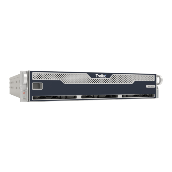
EX Series The EX 8600 The EX 8600 The FireEye EX 8600 protects your network from spear phishing attacks that bypass traditional anti-spam technologies. It analyzes every attachment using a signature-less, Multi- Vector Virtual Execution engine that can identify zero-day attacks by detonating attachments in an environment that mimics operating systems, applications, and browsers in their exhaustive list of versions, configurations, and plug-ins. - Page 5 EX Series The EX 8600 Button/ LED Name Description Status Indication Blinking at 4 Hz Checking BIOS/BMC integrity Blinking at 4Hz and "i" LED is blue BIOS firmware updating Two blinks at 4 Hz, one pause 2 Hz and "i" BMC firmware updating LED is blue Blinking at 1 Hz and "i"...
-
Page 6: The Rear View
EX Series The EX 8600 Chassis 1. Disk Drive Carrier: Each carrier can house a hot-swappable disk drive. A drive slot map displays the disk slot numbers on top of the appliance. 2. Handle Release: Press this tab to release the handle. Use the handle to pull the disk drive carrier from the chassis. - Page 7 EX Series The EX 8600 I/O Ports • USB 2.0: These ports are USB 2.0 compliant. • Serial Console: Connect to this port to manage the appliance from your terminal. • Video: Connect a monitor to this port to view the appliance's command-line interface.
-
Page 8: Deployment
EX Series Deployment Deployment You can deploy the EX 8600 in your network in one of the following ways: • Message Transfer Agent Deployment Page 8 • Bcc: Deployment Page 8 • SPAN/TAP Deployment Page 8 Message Transfer Agent Deployment When the EX 8600 is in Message Transfer Agent deployment, it serves as an MTA inline with the email traffic flow and can be configured to Block Analysis Mode or Monitor Analysis Mode. -
Page 9: Bcc: Deployment
EX Series Deployment Prerequisites Before connecting the EX 8600 to your network, ensure that your network devices provide 10/100/1000BASE-T Ethernet output. Cabling Connect two cables to the EX 8600 appliance’s management ports as follows: • ether1: Connect one end of an Ethernet cable to the EX appliance’s ether1 port, and connect the other end to your LAN-facing switch. -
Page 10: Span/ Tap Deployment
EX Series Deployment Prerequisites Before connecting the EX appliance to your network, ensure that your network devices provide 10/100/1000BASE-T Ethernet output. Cabling • ether1: Connect one end of an Ethernet cable to the EX appliance’s ether1 port, and connect the other end to your LAN-facing switch. This port is the management interface. - Page 11 EX Series Deployment The diagram below illustrates the SPAN/TAP deployment of an EX appliance in a typical network environment. IMPORTANT For information about configuring the EX 8600 appliance for SPAN/TAP mode, see the Email Security System Administration Guide for your release. Prerequisites Before connecting the EX appliance to your network, ensure that your network devices provide 10/100/1000BASE-T Ethernet output.
-
Page 12: Installation
EX Series Installation Installation This chapter describes the site requirements of your installation location. Before You Begin Follow the steps in this section before you install the appliance. Before Opening the Box • Review the packing slip contained in the plastic slip attached to the top of the box. Ensure the shipment contains the correct appliance. -
Page 13: Rack Precautions
EX Series Installation Rack Precautions FireEye recommends that you mount the appliance in a standard 19-inch rack. The vertical hole spacing on the rack rails must meet standard ANSI/EIA-310-C requirements. Consider the following before installing your appliance in the rack: •... -
Page 14: Rack-Mounting Precautions
EX Series Installation • Allow hot-swappable power supply units, disk drives, and transceivers to cool before handling them. • Use a regulating uninterruptible power supply to protect your components from voltage spikes, power surges, and failure during a power outage. •... -
Page 15: Cabling Requirements
EX Series Installation Cabling Requirements The EX Series appliance ships with the following cables: • (2) 6 ft AC power cord, SVT, 60oC, 3x18AWG (0.824mm2) • (1) 6 ft null modem DB9 female serial cable You must provide any additional cables required to connect your system to the network and other devices. -
Page 16: Attaching Cables To The Appliance
EX Series Installation 2. Fully slide the appliance into the rack. The inner and outer rails will lock together automatically. 3. (Optional) Further secure the appliance to the rack by using the captive screws installed on the ears of the appliance. Attaching Cables to the Appliance 1. -
Page 17: Replacements
EX Series Replacements Replacements Return Process If you believe you have a defective part or system, you must first contact FireEye Technical Support, who will validate the claim. If the part or system is defective, Technical Support will initiate a Return Materials Authorization (RMA) and guide you through the process. For more information, visit www.fireeye.com/legal. - Page 18 EX Series Replacements 1. Turn off the appliance. 2. Using a Phillips screwdriver, remove the four screws securing the middle section of the appliance’s top cover. 3. Remove the middle section of the top cover. 4. Remove the fan from the appliance by squeezing the plastic release tab and pulling.
-
Page 19: Appendices
EX Series Appendices Appendices Appendix 1: System Specifications The table below provides the technical specifications for the Trellix EX 8600 . Component EX 8600 Specifications Form Factor 2U Rack-Mount Weight of Appliance 41 lbs Weight of Packaged Appliance 67 lbs Dimensions 17.2 x 25.5 x 3.5 inches (43.7 cm x 8.9 cm x 64.7 cm) -
Page 20: Technical Support
EX Series Technical Support Technical Support For technical support, contact FireEye through the Support portal: https://csportal.fireeye.com Documentation Documentation for all FireEye products is available on the FireEye Documentation Portal (login required): https://docs.fireeye.com/ Page 20 © 2022 FireEye Security Holdings US LLC... - Page 21 FireEye Security Holdings US. LLC. | 601 McCarthy Blvd. | Milpitas, CA | 1.406.321.6300 | 1.877.347.3393 | www.trellix.com © 2022 FireEye Security Holdings LLC. All rights reserved. Trellix, FireEye, and Skyhigh Security are the trademarks or registered trademarks of Musarubra US LLC, FireEye Security Holdings US LLC, and their affiliates in the US and /or other countries.
Need help?
Do you have a question about the FireEye EX Series and is the answer not in the manual?
Questions and answers