Precision Planting 20/20 Operator's Manual
Gen3 air seeders
Hide thumbs
Also See for 20/20:
- Operator's manual (144 pages) ,
- Operator's manual (65 pages) ,
- Setup manual (8 pages)
Table of Contents
Advertisement
Quick Links
Advertisement
Table of Contents

Related Manuals for Precision Planting 20/20


Summary of Contents for Precision Planting 20/20
- Page 1 Operator’s Guide — Air Seeders For Gen3 20|20 Displays 955725_4 3/15/22...
-
Page 2: Table Of Contents
Contents 20|20 Monitor Overiew ........................5 Cab Installation..........................8 Powering the 20|20 On and Off......................10 Cab Control Module [CCM] ......................11 Home Screen Overview........................12 Controlling the Map .........................13 Dashboard Mini Chart ......................15 Individual Row Details......................16 Notification Center ........................17 Summary Information ......................18 Connectivity ..........................19 Speed &... - Page 3 Air Seeder Equipment Setup ....................40 Air Seeder Cart Equipment Setup ....................44 Save/Load ..........................45 Systems Menu ..........................46 Systems Setup...........................46 Bus Device Setup Examples.....................49 Tower Style Seeder........................49 CCS/Drill Style Example ......................51 Systems – Down Force......................54 Systems - Granular Products ....................57 BXM Setup Example........................60 Diagnose ............................61 Calibration ............................64 Settings ............................65...
- Page 4 Delete............................68 Wi-Fi............................69 General .............................69 About ............................69 Appendix Index ..........................70 Appendix A — Understanding the Home Screen Metrics ............71 Appendix B..........................74 Appendix C..........................76 Appendix D ..........................77 Appendix E..........................78 955725_4...
-
Page 5: 20|20 Monitor Overiew
SmartFirmer, vDrive Insecticide, vApplyHD, FlowSense, vSet Select, mSet, SeederForce, Smart Connector, and YieldSense. Software Updates Precision Planting will continue to update and improve the 20|20. Software updates are free of charge and can be downloaded from www.2020.ag and installed on the display with a USB drive. - Page 6 20|20 Hardware Overview Either one or two displays can be connected to the Display Base Module at any time. One of these two displays can be an iPad running the Climate Corporation FieldView Cab app. Displays can be mounted in any location within the cab. Display Base Module [DBM] The Power over Ethernet [PoE] ports requires a Shielded Twisted Pair [STP] Ethernet Cable to connect to a display.
- Page 7 Indicator Light Overview Color Display Base Module Display FieldView Module Good Connectivity Good Connectivity Good Connectivity Green Initializing Downloading Software White Blinking White Firmware Update in Process No Connection between Yellow Initializing Initializing Display and DBM Software Update In Blinking Software Update in Software Update in Progress...
-
Page 8: Cab Installation
Cab Installation Step 1: Mounting locations will vary from tractor to tractor. Mount the display or both displays for optimal visibility and interaction for the operator. There are several mounting options offered by Precision Planting available for the display. The diagram depicts the display with a RAM mount. - Page 9 Step 3: Connect the 725150 Power Harness to the DBM into the 4-pin Deutsch Connector on the DBM and then to the power source in the tractor cab. A three pin round convenience port connector is provided to plug directly into a standard convenience port. Various adapters are available to connect to different types of power ports.
-
Page 10: Powering The 20|20 On And Off
Step 5: Connect the 725155 Speed Harness to the 8-pin Deutsch connector on the DBM. This will provide you with two 4-pin round connections. The male pin connector will connect to the GPS adapter, while the female pin connector will connect to the Radar adapter. -
Page 11: Cab Control Module [Ccm]
Cab Control Module [CCM] The CCM is installed below the display. If two displays are being utilized only one CCM should be installed (it does not matter which display it is connected to). All planter control products being run through the 20|20 require a CCM to be installed as it has a Master Plant switch and swath control features. -
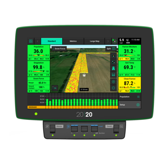
Page 12: Home Screen Overview
Home Screen Overview The Home Screen displays seeding information in an easy to read, easy to navigate format. This information is presented as both metrics and high definition maps. There are three different home screen configurations that can be quickly selected to change the layout of the home screen. All three screens can be customized with different types of measurements, button sizes, map sizes, control buttons, and minichart. -
Page 13: Controlling The Map
Selecting the Map Type name (e.g. Coverage) at the top of the map will display the Map Layer Selection screen. All map types are listed on this page (the systems installed and configured will determine which map types will build a map). Map types are categorized by General, Air Seeder, and Seed. - Page 14 • A third way to change the map orientation is to place two fingers on the map and rotate the map. Rotating the map in this style will lock the map into the orientation that it was rotated to. To switch back to North Facing press the compass button.
-
Page 15: Dashboard Mini Chart
• Map types can be changed at any time by selecting a different type. • Some map types require specific Precision Planting products to be installed on the planter to generate the information necessary to create a map. • If the map has moved away from the tractor/seeder location, a white arrow will appear on the edge of the map pointing to the direction the tractor/seeder is in. -
Page 16: Individual Row Details
On the selection page a larger Row by Row chart will be displayed. On the Navigation Pane on the right hand side of the screen, select a different metric type to be displayed. Additional metrics are available if you use a finger to scroll the Navigation Pane downward. Once a different metric has been selected, press “Home”... -
Page 17: Notification Center
Notification Center The Notification Center is designed to alert the operator of issues. The Notification Center button on the home page will give a number indicating the number of Event Codes that have taken place since the last reset. Press the button to display all event codes and a description of the issue. -
Page 18: Summary Information
Summary Information Summary information for the active field can be found by pressing any of the different acre counters on the home screen or the Field Summary button under Field Setup (Setup — Fields). When an acre counter is selected, the “Counter Details”... -
Page 19: Connectivity
Connectivity Speed & GPS Speed The top right hand corner of the home screen displays the current speed of the tractor. The bars under the speed source icon indicate signal strength. The icon itself will be white if the speed source state is good. - Page 20 GPS Communication “Reconnect to GPS Receiver” button is located in the bottom left of this page. Press this button to force the system to try to reacquire the GPS signal. GPS Nudge and Corrections The GPS Corrections page can be used to configure how the system handles the GPS signal.
-
Page 21: Customizing The Home Screen
Customizing the Home Screen Customizing the Home Screen To begin the process of customizing the home screen, select the button in the top left hand corner of the screen. When pressing this button the home screen will be dimmed with a grid pattern laid on top. - Page 22 Metrics: The metrics are all of the buttons that display planter information on the home screen. Metrics can be displayed in five different sizes: Small (1x1), Wide (2x1), Tall (1x2), Large (2x2), and Extra Large (3x3). Not all metrics are available in Large and Extra Large.
- Page 23 Dashboard Minichart: Add either a Dashboard Minichart to the home screen or a Swath Control bar. This page offers both in two different sizes: full and ¾. The Full size will stretch across the entire bottom of the display while the ¾ size, will leave a space on the left side where additional buttons can be added.
-
Page 24: Setup Button
Setup Button Press the Setup button on the home screen to access the main navigation screen for equipment and control systems’ setup, diagnostic, and data pages. This page is divided into information about the system including diagnostics, information about products being applied, and the main navigation pane. - Page 25 When navigating through different screens, there will always be a “Back” button that will navigate the user to the previously viewed page. The “Home” button will navigate the user to the main home screen. 955725_4...
- Page 26 Basic Overview of the Main Navigation Menu Fields: Change the active field name, assign prescription/boundary to a field, and create or edit Client, Farm, & Field names. Products: Assign active crop. Alerts: Configure limits and settings for control and monitoring for each crop or implement wide. Equipment: Configure the implement profile, implement measurements, and tractor measurements.
-
Page 27: Fields
Example of a bread crumb trail: Fields Precision Planting uses a three tiered naming structure for field names: Client, Farm, & Field. Each tier of the naming architecture becomes more specific. At all times there will be an active field. The active field (a field consists of a Client, Farm, and Field name) is the field in which all data and map is being created for and stored under. - Page 28 To view different field names, select a different Client or Farm name. Select either the Client or Farm name displayed towards the top of the page to select a different Client or Farm. When the Client box is selected, a list of all Client names is displayed.
- Page 29 The 20|20 can use prescription files for Seeding (vDrive), Liquid application (vApplyHD), and Insecticide (vDrive Insecticide). The Field Setup page will change with the type of products configured. See following information in this document for importing and assigning prescriptions. Note: The option to assign a prescription will not be available unless a Seeding/Liquid/ Insecticide system is setup on the display.
- Page 30 Next, select what system type the Prescription file(s) will be used for. Options include • Seeding • Liquid • Granular • Depth Finally, Select what prescription files need imported. If prescription files are being used for multiple systems, complete the above process for each system type. Assigning Prescription Files Once Prescription files have been imported into the 20|20, each file will need to be assigned to its...
- Page 31 Controlling to Prescription Files After the active field has a prescription file assigned to it, the system can use a prescription file for control. This applies to the following systems: • Seeding • Liquid • Granular • Depth To switch to prescription control, follow the below steps: 1.
- Page 32 After the desired attribute and zones are selected, you can either adjust it by a percent, or bump the values up or down using the + or - buttons on the screen. Once the prescription has been edited, tap on 'Cancel' to discard any changes made, or tap on 'Save' to save the changes made to the prescription.
-
Page 33: Products (Crops)
Products (Crops) To configure monitor settings for individual crop types, select the “Products” menu button from the navigation pane. To change the active crop type, select the “Active Crop” button at the top of the page. If the desired crop type is not available, select the “Add Crop” button at the bottom of the main Crops page to view a list of all crop types that can be added to the list. - Page 34 Ground Contact Alert Limit- This will set the point at which the Ground Contact metric will turn yellow, indicating that loss of Ground Contact may begin to have an agronomic affect.. Ground Contact Failure Limit- This will set the point at which the Ground Contact metric turns red.
- Page 35 Magnitude Failure Limit - This will set the point at which the Magnitude metric turns red. Particles per Pound - Metric used to calibrate the monitoring system according to seed size. Default is 10,000. Deviation Alert Limit - This will set the point at which the Deviation metric will turn yellow. Particles to Average -Defines the number of particles used in the rolling average of seed data to calculate Magnitude, Deviation and Uniformity.
-
Page 36: Equipment Menu
Equipment Menu The Equipment menu is where the Air Seeder and tractor are configured. Adding a New profile will override existing setup. Save current configuration before changing implement type. See Save/Load for more details Click “New Profile” to create a new tractor and air seeder profile. -
Page 37: Tractor Equipment Setup
Tractor Equipment Setup Tractor Information and Measurements are entered under the Tractor Profile Page. From the home screen select Systems – Equipment – Edit Tractor. The first page shows general tractor settings, including: • Make • Model • Steering — Front, Articulated, or Track. •... - Page 38 Steering Type: Front A - Hitch: Measure the distance from the center of the rear axle the hitch (or pivot point on a two point pivot planter hitch). Note: If a 3 pt planter hitch is connected, enter 0. B - Center: Measure the distance from the center line of the tractor to the GPS output location.
- Page 39 Steering Type: Tracked A - Hitch: Measure the distance from the pivot location to the hitch (or pivot point on a two point pivot planter hitch). B - Center: Measure the distance from the center line of the tractor to the GPS output location. Then select if the GPS output location is to the left or right side of the tractor's center line.
-
Page 40: Air Seeder Equipment Setup
Air Seeder Equipment Setup From the Equipment Setup page, press the “Edit Air Seeder” button to configure the monitor according to your air seeder. Setup > Equipment > Edit Air Seeder AIR SEEDER DETAILS (Tab 1) The first screen will be Air Seeder Details, or the general settings for the Air Seeder. These settings include •... - Page 41 Select the appropriate number of ranks under the Frame Type. This defines what measurements can be entered in the Air Seeder Measurements tab. The rest of the Air Seeder specs, such as row number and spacing, are under the Air Seeder Details (Tab 5).
- Page 42 AIR SEEDER MEASUREMENTS (Tab 4) The Air Seeder Measurements Tab 2 sets the measurements for the Air Seeder frame ( wheel and hitch distance), and the Air Seeder Measurements Tab 4 sets the measurements for the Ranks (seed exit and offsets). Depending on how many seeding ranks are selected, two to four different measurements will need to be entered into the system.
- Page 43 AIR SEEDER DETAILS (Tab 5) The Air Seeder Details Tab 5 page includes the follow options: • Rows • Spacing • Active Rows • Controlled Row Spacing • Controlled air Seeder Width • Press the “Rows” button to enter the correct number of physical rows on the Air Seeder. Press the “Spacing”...
-
Page 44: Air Seeder Cart Equipment Setup
AIR SEEDER SYSTEMS (Tab 6) Air Seeder Systems must be added here before they can be further configured in Setup > Systems. Systems include Seeding, Force, Liquid, and Granular (labeled “Categories” on this page). Each system can then have a Product or multiple Products assigned (labeled as “Systems” on this page). -
Page 45: Save/Load
CART DETAILS Select the appropriate make and Hitch Type. CART MEASUREMENTS Wheel Distance— Enter the distance from the pivot point to the center of the rear frame wheel axle Hitch Distance(In-between Carts Only) — Enter the distance from the rear axle to the rear hitch. Width —... -
Page 46: Systems Menu
Systems Menu The Systems menu contains setup for all Systems and Products installed. The available options in the System menu will change depending on what Systems (e.g. DownForce, Granular etc…) and Products (e.g. Nitrogen, Starter, Wheat) are configured in the equipment menu. Each control products’... - Page 47 Bus Assignment - Select each CAN network and assign the total number of SRM backbone connectors that are being used on that network. Total SRM Backbone Connectors include all the connectors where an SRM or BXM is installed. Repeat this for each CAN Bus Network. Refer to Appendix B (Tower Style) or Appendix C (CCS/Box Drill Style) for charting correct module assignments.
- Page 48 Add Hardware – Once Bus Devices have been set up, click “Add Hardware” to add other hardware such as Lift Switch. Cab Control Module — The CCM section switches, or middle 3 switches, can be configured to control custom percentages of the implement. Adjust the sliders or tap the boxes to enter a custom percentage.
-
Page 49: Bus Device Setup Examples
Bus Device Setup Examples Tower Style Seeder The sample below from the Module Index Worksheet – Tower Style Seeder (Appendix B) is from an Air Seeder with 5-row towers. Fill out the worksheet as follows: Step 1: Indicate the Tower No. the backbone is installed on. Step 2: In “Module Type”... - Page 50 Step 4: Starting at the 1 backbone, create an index of every module connected to each CAN network (“Module Number” column). If any connectors have row plugs, skip that row. Continue numbering sequentially through the end of the CAN network (note red arrow). Repeat same process for additional CAN networks.
-
Page 51: Ccs/Drill Style Example
CCS/Drill Style Example The sample below from the Module Index Worksheet – CCS/Box Drill Style Seeder (Appendix C) is from an Air Seeder with 38 rows split into 2 CAN networks, CAN A (red line) and CAN B (Blue line), with four Blockage Expansion Modules (BXMs). In the above scenario, the Module Index Worksheet –... - Page 52 Step 4: For each CAN network, number sequentially on the “Module Number” row for each backbone connection that has a module present. Using the above example, configure the Bus Devices on the 20|20 as follows: CAN A Module Assignment: CAN A Module Location: Backbone Connector 1 –...
- Page 53 Included below is another configuration example, for a Rockshaft controlled system rather than row by row SeederForce which would have a SRM on every row. 955725_4...
-
Page 54: Systems - Down Force
Systems – Down Force When a DownForce system has been added in Equipment it will appear on the Systems menu, select DownForce on the Systems screen to configure. Select “Control Sections” and make sure all rows are assigned to a section (in most scenarios all rows can be assigned to one section.) Click on “Add Hardware”... - Page 55 SEEDERFORCE ROW SOLENOID- Row by row SeederForce Systems Select Add Hardware and select SeederForce Row Solenoid. Select the Rows that have a SeederForce Solenoid (Cylinder) on them, and then click Continue Cylinder Type and Max DownForce can be specified on each row. The only cylinder type available is “SeederForce Single Row”.
- Page 56 DOWN FORCE SENSOR Select “Add Hardware” and select “Down Force Sensor”. Select the rows that have a down force sensor on them. Refer to Appendix E. Change the Sensor Type to 735100 for all Seeder down force sensors. Although the calibration offset can be manually adjusted, it should always be set through the Zero Down Force Sensors Calibration and not manually adjusted unless otherwise directed by Product Support.
-
Page 57: Systems - Granular Products
Systems - Granular Products Click on products (Nitrogen and Wheat in example to the right). Control Sections - verify all rows are assigned to a section. Coverage Overlap – select coverage overlap; Full Row, ½ Offset, No Offset Start/Stop Offset – adjustment of application start and stop timing. - Page 58 Coverage Pattern – setting for when application swaths off into diagonal coverage area. Delivery Offset – adjustments for distance between application position and main discharge position. Active Rows – allows user to activate only select rows. 955725_4...
- Page 59 ADDING HARDWARE Click on “Add Hardware” to add any hardware associated with product. Any product monitoring blockage sensors will need the BXM hardware set up. For each module (selected in “Module on Row” column) assign each Input a Row. (The BXM locations are pre-determined by the Bus Devices Configuration.) Note: In some applications a BXM may have...
-
Page 60: Bxm Setup Example
BXM Setup Example The sample below from the BXM Port Assignment Worksheet (Appendix D) is from an Air Seeder with 8-row towers. Fill out the worksheet as follows: Step 1: Assign a Tower # to each BXM; this numbering could be based on the manufacturers numbering system, or a custom system. -
Page 61: Diagnose
Diagnose The Diagnose Menu is the primary location for trouble shooting issues related to the operation of the 20|20 system itself and all products configured on the monitor. This is the initial diagnose page. Each product or system that is configured is displayed along with a row unit showing a drawing of the product(s). - Page 62 When on the 1st level diagnose page, either Air Seeder or Tractor can be selected. All Air Seeder products (BXM, Downforce, etc) are under the Airseeder tab, while components that are in the Tractor cab are listed under “Tractor”. The tractor components include the DBM, Cab Control Module, and GPS COLOR LEGEND...
- Page 63 System Schematic - The system schematic is a tree-style overview of all products setup or communicating with the 2020. Select the arrow on each box to show or hide rows. The system schematic shows the location and Product name for each module, as well as the state — signified by color.
-
Page 64: Calibration
Calibration Calibration on the Setup Menu will allow the user to perform tests and calibrations based on the products and systems installed. Tests and calibrations available may include GPS Offset Check, Lift Switch Calibration, Radar Calibration, see below for further descriptions of these tests. -
Page 65: Settings
Display Base Module and Display. Install from USB – Software can be downloaded for free from the Precision Planting website and saved to a USB drive. Ensure the software file is on the root directory on the USB drive. Place the USB drive in the side of the display and then select “Install from USB”. -
Page 66: 20|20 Cloud
20|20 Cloud Allows the user to login into their 20|20 cloud account and visualize satellite background map. Registration is required before logging into the cloud from the Gen3. Once logged in, the user can backup data to the cloud by toggling on “Cloud Backup Enabled”. -
Page 67: Import Data
the display that the USB is connected to will export the Display Config. Each display will have its own config. Field Map Data – Displays a list of all data for all implement types. Data is organized by Name, Data Size, Acres, Season, and Pass. Only fields that have data will be displayed. -
Page 68: Delete
Third Party – Import files created from a third-party setup file, including Client, Farm, Field setup, and prescriptions and boundaries. 20/20 Gen2 Setup – Import, Client, Farm Field setup from a 20/20Gen 2. Restore Configuration – Monitor Configurations are automatically backed up and saved by date. -
Page 69: Wi-Fi
Wi-Fi Allows the user to connect to any password protected wifi network. Note: Wifi network must be a secure network (password protected). General Allows the user to change display configurations. • Language • Units — Imperial or Metric • Cab Control Module — Present or Not Present (Must be present for most control systems) •... -
Page 70: Appendix Index
Appendix Index Appendix A - Understanding Blockage Monitoring Metrics Appendix B - Module Index Worksheet — Tower Style Seeder Appendix C - Module Index Worksheet — CCS/Box Drill Style Seeder Appendix D - Blockage Expansion Module (BXM) Input Assignment Appendix E - SeederForce Rockshaft Worksheet For Tower Style Seeders, use Appendix B and D For CCS/ Box Drill Style Seeders, use Appendix C and D... -
Page 71: Appendix A - Understanding The Home Screen Metrics
Appendix A — Understanding the Home Screen Metrics Blockage Monitoring Metrics Defined Note: “Product” will be replaced by system’s nickname as defined by the user. “Product” Magnitude A relative measurement comparing the amount of a product being applied in a given area. Value Range: 0-10,000 k Use Case: A row by row comparison of the amount of product being applied. - Page 72 Available Widgets: User inputs: Set by grower selecting alerts/alarm percentages. Alert (Yellow) number and Alarm (Red) number. Note: Alerts (will come later) - 10%, 20%, 30%, 40%, Custom, Disabled. “Product” Deviation A measure of how uniform the product magnitude is across the implement, showing both greater than and less than rates.
- Page 73 “Product” Rate State Maps the “state” of each row; ie. healthy (green), alert (yellow), alarm (red). Use Case: gives a historical and geographical reference of alerts and alarms while operating in the field. Available Widgets: Blockage Simple status of particles being detected or not detected. Green indicates a sensor pulse has been detected in the last “n”...
- Page 74 Appendix B 955725_4...
- Page 75 955725_4...
- Page 76 Appendix C 955725_4...
- Page 77 Appendix D 955725_4...
- Page 78 Appendix E 955725_4...
Need help?
Do you have a question about the 20/20 and is the answer not in the manual?
Questions and answers