
Related Manuals for TOOL WAREHOUSE WT-SBC990


Summary of Contents for TOOL WAREHOUSE WT-SBC990
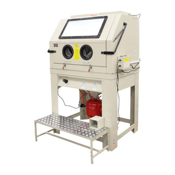
- Page 1 WT-SBC990 990L CAPACITY INDUSTRIAL CABINET SANDBLASTER OPERATING AND MAINTENANCE INSTRUCTIONS...
-
Page 2: Technical Specifications
TECHNICAL SPECIFICATIONS : Nozzle size:6/6/7/7MM Motor power:1200W Air compressor delivery: 125PSI@24CFM Overall dimensions: 52"x49"x70" Working space: 46"x35"x33" Air hose: φ12*(1000mm&1300mm) Sand hose: φ19*1500mm Page 1 of 12... -
Page 3: Important Warning
IMPORTANT WARNING READ ALL INSTRUCTIONS BEFORE USING THIS EQUIPMENT. SAVE THESE INSTRUCTIONS FOR FUTURE REFERENCE. Due To Continuing Improvement, Actual Product May Differ Slightly From Product Described Herein. Remember 1. START UP PREPARATIONS: The I.D of air line should be more than 8mm (0.3”). ALL Hoses Should Be Rated At Least 125psi (8.6bar) And An Isolation valve should be installed so that supply air can be turned off and then disconnected from sandblaster cabin for servicing. - Page 4 Nor are representations made or intended to the useful life, maintenance cycles, efficiency or performance of the referenced products of any combination of products. This material must not be used for estimating purpose. Production rates, labor performance or surface finished are the sole responsibility or the user based on the users expertise, experience and knowledge of industry variables.
- Page 5 STEP <1> 1.Please upend the bracket (#8), use M8*20 hex bolt(match faced washers, spring washers) to pass leg A (3pcs), leg B (#10)(1PC), then mount on the bracket as figure showed. Please take care the deposited position & direction of leg B(#10) 2.Please use M8*20 hex bolt and faced washers, spring washers to pass leg reinforce 1,2.
- Page 6 Step<3>: 1.Please place the upper cabinet on the assembled Step<2> as figure. Please notice that front of upper cabinet should be put to face leg B. 2.Opening the double folded door, combine the upper cabinet, big funnel & bracket in one whole by 22pcs M6*16 round head screws and faced washers.
-
Page 7: Maintenance Instructions
3. Please place the left / right grid in the upper cabinet. 4. Remove the sandblaster to the right position by forklift, then remove the reinforce of front leg. OPERATING INSTRUCTIONS preparing parts for blasting all parts processed must be free of oil, grease and moisture. Make sure parts are dry before putting into the cabinet for cleaning. - Page 8 corrected media will not flow evenly and will plug up in the metering valve and the gun. Check air supply; if water is present installed a good moisture trap. If oily or greasy parts are being blasted, you should degrease and dry the parts first. reverse pressure if media stops flowing occasionally, place thumb over nozzle (hold tight) and push foot pedal down for a couple of seconds.
- Page 9 replace existing gauge if you suspect it is giving you false readings. blast gun the nozzle will wear out eventually. Replace it if it's measured 1/16 over its original size or if it shows uneven wear. Adjust as needed for different media and conditions. A properly working gun will pull 15-17 inches of mercury on manometer.
-
Page 10: Parts Diagram
PARTS DIAGRAM-1 Page 9 of 12... - Page 11 PARTS DIAGRAM-2 Page 10 of 12...
-
Page 12: Parts Listing
PARTS LISTING ITEM# DESCRIPTION QUANTITY Upper cabinet Round head cross screws (matched washers) Suction sand hose Left grid Right grid Sealing tape Big funnel Bracket M8*20 Leg B Permanent seat of pneumatic device Pressure gauge/ Each 1 Pressure regulating valve Assembled latches Welded cover board for falling sand Pneumatic device of foot pedal... - Page 13 Mounting ring of gloves Glove seats Gloves 1 pair Front operation board /sand board Elements of front opening door Cap of nozzle Nozzle "O" seal ring Gun body Sheath of air jet pipe Lock nut Air jet pipe 12-G1/4" quick straight-pass connector Conversion connector Air hose φ12xφ8 Quick fitting G3/8"...
Need help?
Do you have a question about the WT-SBC990 and is the answer not in the manual?
Questions and answers