Advertisement
Quick Links
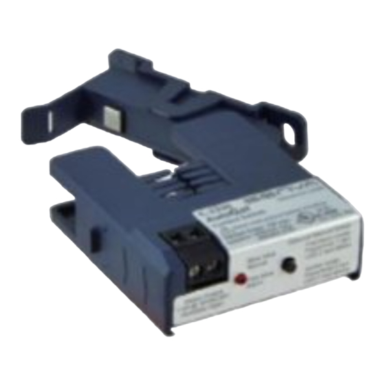
INSTALLATION INSTRUCTIONS
C-2330,
Auto-Calibrating
Mini Split-Core Digital
Output
Not for use on variable speed drives.
Use C-2350-VFD for VFD applications.
DANGER
Failure to follow these instructions will result in
Hazard of electrical shock, explosion,
and arc flash
!
WARNING
death or serious injury.
•
Follow ALL requirements in NFPA 70E for safe work practices
and for Personal Protective Equipment (USA) and other appli-
cable local codes when installing this product
•
Only qualified electrical personnel should install this product.
•
Read, understand, and follow all instructions thoroughly
DANGER
•
Install only on insulated conductors
•
Lock out and tag out all power sources prior to installation.
Use properly rated voltage sensing instrument to determine
no voltage is present
!
WARNING
Failure to follow these instructions could result in
death or serious injury.
Automated equipment may
start without warning
•
Equipment monitored/operated by this device may start
without warning. Keep clear of apparatus at all times
IMPORTANT WARNINGS
•
Only qualified trade installers should install this product
•
This product is not intended for life-safety applications
•
Do not install in hazardous or classified locations
•
The installer is responsible for all applicable codes
•
This product must be installed in a suitable electrical enclosure
senvainc.com 1-866-660-8864 (F)1-503-296-2529 9290 SW Nimbus Ave. Beaverton Oregon 97008
1. Determine mounting location for the sensor near the
conductor to be monitored. The sensor should be located AT
LEAST 1/2" from any uninsulated conductor.
2. Sensor features a flexible iris which allows the sensor to
hang on the conductor if local codes permit. A bracket is
included for screw mounting or attaching to DIN rail. For screw
mounting, drill two 3/32" pilot holes using the bracket as a
template; ensure no drill shavings are present in enclosure. At-
tach bracket with screws provided.
3. Clamp sensor around INSULATED CONDUCTOR ONLY,
3PZS
600VAC MAX to be monitored.
4. Snap the sensor into the mounting bracket.
5. Wire the output of the sensor to a control panel digital
input loop not to exceed 30VAC/DC wetting voltage. Tighten
terminals to 3.5 in-lb.
1. No calibration is necessary for normal applications. Sensor
will automatically learn motor run current and adjust threshold
as needed.
2. To manually re-calibrate sensor, press and hold button for 1
second. LED will blink twice. Sensor will discontinue automati-
cally threshold adjustment.
3. To set sensor to go/no mode, press and hold button for 5
seconds. LED will blink 3 times.
CONTROLLER
V+
V+
DI
DI
(SINKING)
CONTROLLER ARRANGEMENTS
V+
DI
(SOURCING)
PRODUCT APPLICATION LIMITATION:
Senva products are not designed for life or safety applications. Senva products
are not intended for use in critical applications such as nuclear facilities, human
implantable device or life support. Senva is not liable, in whole or in part, for
any claims or damages arising from such uses.
INSTALLATION
Disconnect, lock out and tag out all
power supplies during installation
CALIBRATION
WIRING EXAMPLES
NOTE: Device is NOT polarity sensitive.
Slow blink
Normal
Fast blink
Status Output
Alarm
0.5A @ 30VAC/DC
Normally Open
ALTERNATE
DI
DI
VAC
DI
24VAC
GND
(AC)
INSULATED PRIMARY
AC CONDUCTOR
600VAC MAX
Optional Manual Setup:
Fast learn mode:
Press/hold 1 sec
LED 2 fast blinks
Go/No mode:
Press/hold 5 sec
LED 3 fast blinks
Advertisement

Related Manuals for senva C-2330

Summary of Contents for senva C-2330
- Page 1 • The installer is responsible for all applicable codes implantable device or life support. Senva is not liable, in whole or in part, for any claims or damages arising from such uses. •...
- Page 2 Load “OFF” For use in Pollution Degree 2 Environment. Sensor Output Energized Output The C-2330 output is closed whenever motor run current exceeds Part Number C-2330 learned setpoint. Setpoint adjusts automatically over time to compen- Amperage Range 2.5A (on)~135A (200A Max.)
Need help?
Do you have a question about the C-2330 and is the answer not in the manual?
Questions and answers