
Related Manuals for ELTEC CYBOX GW 2-P

Summary of Contents for ELTEC CYBOX GW 2-P
- Page 1 CYBOX GW 2-P MOBILE WIRELESS GATEWAY WITH 5G AND WI-FI 5 / WAVE 2 INSTALLATION MANUAL Revision: 1.3 | Date: 04.11.2022...
- Page 2 CYBOX GW 2-P LIST OF CHANGES ISSUE CHANGE DESCRIPTION DATE Initial version 2022-07-25 Adoption of antenna description / Added chapter mezzanine 2022-07-26 extensions Chapter correction 2022-08-01 Chapter mezzanine extensions extended 2022-11-04...
- Page 3 The complete risk inherent in the utilization of this document or in the results of its utilization shall be with the user; to this end, ELTEC Elektronik AG shall not accept any liability. Regardless of the applicability of respective copyrights, no portion of this document...
- Page 4 EU DECLARATION OF CONFORMITY ELTEC Elektronik AG herewith declares that the device is compliant to the basic requirements of the directive 2014/53/EU. The full text of the EU declaration of conformity is available in the Download Center at www.eltec.com.
- Page 5 CYBOX GW 2-P CONTACT ELTEC Elektronik AG Galileo-Galilei-Straße 11 55129 Mainz Germany +49 6131 918 100 +49 6131 918 195 Email info@eltec.com www.eltec.com...
-
Page 6: Table Of Contents
CYBOX GW 2-P CONTENTS ABOUT THIS DOCUMENT OVERVIEW Products HARDWARE Device Connectors 3.1.1 Power Supply Connector 3.1.2 M12 Ethernet Interfaces 3.1.3 M12 Service Interface (USB and Serial Port) Mezzanine extensions 3.2.1 MVB Interfaces 3.2.2 2.5 Gbps Ethernet Interface 3.2.3 M.2 PCIe SSD Extension... - Page 7 CYBOX GW 2-P LIST OF TABLES Table 1 Pin Assignment of Power Supply Connector (PWR) Table 2 Pin Assignment of M12 Ethernet Connectors (LAN 1/2) Table 3 Pin Assignment of M12 Service Connector Table 4 Pin Assignment of MVB Connectors Table 5 Pin Assignment of 2.5 Gb M12 Ethernet Connector (LAN 3)
- Page 8 CYBOX GW 2-P LIST OF FIGURES Figure 1 Picture of CyBox GW 2-P Figure 2 Example M.2 PCIe SSD Figure 3 Examples of Front Panels Figure 4 SIM Slot Assignment per Modem Figure 5 Dimensions of the Housing Figure 6...
-
Page 9: About This Document
CYBOX GW 2-P ABOUT THIS DOCUMENT This installation manual is intended only for system developers and integrators. It is not intended for end users. It describes the hardware functions of the product, connection of peripheral devices and integration into a system. Additional information on special applications and the configuration of the product is available in a separate configuration manual which can be downloaded from the Download Center at www.eltec.com. -
Page 10: Overview
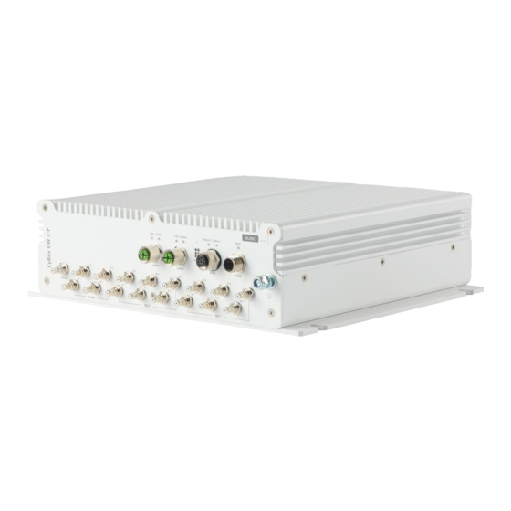
CYBOX GW 2-P OVERVIEW 2.1 PRODUCTS This installation manual comprises all information to set-up the following product. Figure 1 Picture of CyBox GW 2-P... -
Page 11: Hardware
POWER SUPPLY CONNECTOR The CyBox GW 2-P can be powered by a DC power source connected to the internal power supply and I/O connector, shown in Table 1 . The nominal input voltage can vary between 24 V and 110 VDC. The electrical power can be supplied to the device using the A-coded M12 power connector, labeled PWR. -
Page 12: M12 Service Interface (Usb And Serial Port)
3.1.3 M12 SERVICE INTERFACE (USB AND SERIAL PORT) The CyBox GW 2-P is equipped with a M12-A coded USB/serial port. The USB port can be used to attach a memory device to update the firmware or to configure the device. -
Page 13: Mezzanine Extensions
3.2.1 MVB INTERFACES The MVB interfaces of the CyBox GW 2-P are utilizing D-Sub 9 connectors. Two MVB connectors are available (in and out) to connect one MVB device. Both MVB connectors provide the same MVB signals so that a typical MVB bus topology connection can be realized. The pin assignment is shown in Table 4 below. -
Page 14: Gbps Ethernet Interface
3.2.2 2.5 GBPS ETHERNET INTERFACE The 2.5 Gb LAN port extension of the CyBox GW 2-P is utilizing an M12 X-coded connector with the pin assignment as shown in Table 5. Mating connectors are available from several manufacturers. SIGNAL NAME... -
Page 15: Antenna Connectors
CYBOX GW 2-P 3.3 ANTENNA CONNECTORS The QLS antenna connectors are located at the lower part of the front panel. All connectors are labeled for each radio interface and GNSS. When connecting an antenna to the QLS connector, make sure that you hear a ‘click’ sound confirming proper mounting. -
Page 16: Front Panel And Module-To-Antenna Connections
CYBOX GW 2-P 3.4 FRONT PANEL AND MODULE-TO-ANTENNA CONNECTIONS The figure below provides some examples of different front panel versions. Figure 3 Examples of Front Panels... -
Page 17: Correlation Front Panel Labelling - Software
CYBOX GW 2-P 3.4.1 CORRELATION FRONT PANEL LABELLING – SOFTWARE The ports and LEDs “LAN 1” and “LAN 2” correspond to the interfaces “eth0” and “eth1” • The LEDs “Module 1” to “Module 4” refer to WLAN and/or 5G/LTE modules •... -
Page 18: Led Indicators
CYBOX GW 2-P 3.5 LED INDICATORS The LEDs on the front panel of the CyBox GW 2-P provide quick indication of the device status. 3.5.1 POWER LED STATUS LED COLOR STATE DESCRIPTION Green Device is receiving correct input power Green... -
Page 19: Module 1-4 Led Status
3.6 RESET SWITCH The CyBox GW 2-P is equipped with a hidden reset switch behind the front panel, close to the LEDs. The button is accessible with a straightened paper clip pushed through the little hole on the front panel. The effect of pressing the reset switch depends on the duration of its activation, as indicated in Table 12 below. -
Page 20: Sim Cards
The Cybox GW 2-P provides 4 SIM slots per 5G/LTE modem. Only one slot per modem can be active at any time. To install SIM cards the back panel of the CyBox GW 2-P has to be removed using a suitable torx 10 screwdriver. -
Page 21: Mounting
CYBOX GW 2-P MOUNTING When mounting the CyBox GW 2-P please take the following aspects into account. Do not install the device close to any sources of heat such as radiators or heat registers. • Keep the device away from any liquids and avoid exposure to dripping or splashing. The protection •... -
Page 22: Connecting An Earthing Cable
CYBOX GW 2-P 4.1 CONNECTING AN EARTHING CABLE A M6 earthing stud on the front panel of the device (also refer to Figure 1) for protective earth connection is essential for the device security. Carry out the following steps to connect an earthing cable: Use an earthing cable with a cross-section of at least 2.5 mm²...
Need help?
Do you have a question about the CYBOX GW 2-P and is the answer not in the manual?
Questions and answers