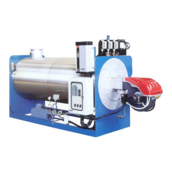
Summary of Contents for IVAR GV
- Page 1 TECHNICAL MANUAL INSTALLATION, USE AND MAINTENANCE INSTRUCTIONS STEAM BOILER...
- Page 2 Dear Customer, Thank you for choosing a boiler by IVAR. In your interest and to maintain the highest level of performance and duration of your appliance, we recommend that you follow the instructions contained in this booklet and have regular maintenance performed by qualified personnel.
-
Page 3: Table Of Contents
CONTENTS page 4 – GENERAL WARNINGS page 5 – GENERAL SAFETY RULES page 6 – “GV” BOILER TECHNICAL SHEET page 7 – “GVO” BOILER TECHNICAL SHEET page 8 – HANDLING AND POSITIONING page 9 – PLANT TYPE page 10 – STARTING UP OF THE BOILER page 10 –... -
Page 4: General Warnings
GENERAL WARNINGS This instruction booklet is an integral and essential part of the product. Should the appliance be sold or transferred to another owner, or if you move and leave the appliance behind, always ensure that this booklet accompanies the appliance so that the new owner and/or installation technician can consult This appliance must be used for the purpose for which it was specifically intended. -
Page 5: General Safety Rules
GENERAL SAFETY RULES The use of any component utilising energy power, fuels and water requires that certain fundamental rules be respected, such as: Do not allow children or unskilled people to use the appliance; If you notice smell of gas, do not turn on electric switches, household appliances, telephone or any other objects that could cause sparks. - Page 6 STEAM BOILER (12 bar) type GV Nominal capacity Kcal/h 75000 120000 180000 240000 330000 420000 98,9 237,5 435,3 554,6 Furnace capacity Kcal/h 85230 136400 204600 272750 375000 477300 mbar Furnace pressure Kg/h Steam production n° Electric pump stadi Water content A –...
- Page 7 STEAM BOILER (12 bar) 1 – WATER PUMP 8 – STEAM SAFETY THERMOSTAT 15 – WATER MANOMETER 2 – ELECTRIC ENGINE 9 – STEAM SAFETY PRESSURE SWITCH 16 – START VALVE DISCHARGE 3 – WATER FLOWMETER 10 – BURNER 17 – STEAM TRAP 4 –...
-
Page 8: Handling And Positioning
HANDLING AND POSITIONING For the lifting of the generators GVO, please see the diagram below. L min. 1100 1400 1000 1700 1500 1900 2000 2200 2500 2300 3000 2750... -
Page 9: Plant Type
PLANT TYPE 1 – GVO boiler 10 – max pressure switch 19 – water tank 28 – discharges 2 – water pump 11 – safety pressure switch 20 – steam collector 29 – safety discharge 3 – electric engine 12 – steam thermostat 21 –... -
Page 10: Starting Up Of The Boiler
A) STARTING UP OF THE BOILER A1) Check the hardness of the water : max 0.5 °F. A2) Open drain valve 15. A3) Shut off the delivery valve 13. A4) Switch on the main switch on the electrical panel. A5) Switch on the pump switch on “MANUALE”. Wait the water flows by the drain valve. -
Page 11: Faults And Remedies
FAULTS AND REMEDIES FLOW SWITCH BLOCK The burner goes out. The flow switch block lamp lights up on the control panel. This means lack of water. Check the water level in the service tank. STEAM BLOCK The burner goes out and steam temperature thermometer pointer exceeds 200°C. -
Page 12: Boiler House
BOILER HOUSE A boiler house is generally made up of the following equipment: 1 - The steam boiler itself, complete with burner. 2 - Water conditioning plant, generally composed of a water softener with change of bases and possibly a mattering unit for conditioning products. 3 - Purified water and condensate collecting tank, having a capacity at least one and half times the hourly steam output of the generator. -
Page 13: Boiler Connection
BOILER CONNECTION WATER CONNECTION The hard water reaches the conditioning plant. This must be surrounded by dividing wall; the floor should possibly be made in “gres”; independent drain for backwashing the conditioner. When the softened water leaves the conditioner it must then be forwarded to the purified water and condensate collecting tank. - Page 14 FUEL CONNECTION (see also burner instruction book) These may be three types: a - pipings for light oil (gas oil); b - pipings for heavy oil (fuel oil); c - pipings for gas. Gas oil pipings The pipings conveying oil from the tank to the pump and viceversa, must be made with welded fittings for iron pipings and biconical fittings for copper ones.
-
Page 15: Electric Panel
WARNING It is recommended to purge all the piping which have to be connected to the boiler to ensure that they do not contain any foreign bodies such as fragments of gaskets, welding slag or anything else which might damage the generator equipment before finally connecting it to the boiler! ELECTRIC PANEL The control switches with relevant pilot lamps are installed on this panel. - Page 16 LIST RECOMMENDED SPARE PARTS WATER PUMP Suction valves Delivery valves Valves springs set Valves seat gaskets set Piston gaskets Lid gaskets Head gaskets Manometer in glycerine bath SAFETY Thermometer with electric contacts DEVICE Contacts for thermometer Steam pressure switch Water pressure switch Flow switch Octal relay Magnetic starter with over load and under...
- Page 17 NOTES...
- Page 18 I.VAR INDUSTRY S.r.l. Via S. Pierino, 4 (Z.A.I.) - 37060 Trevenzuolo – VERONA - Italy Telefono 045/6680082 - Telefax 045/6680051 - P.IVA 02835480233 e-mail: info@ivarindustry.it – Web site: www.ivarindustry.it code: ist-GV-GVO-ing rev.00...


Need help?
Do you have a question about the GV and is the answer not in the manual?
Questions and answers