Advertisement
I N S T R U C T I O N S
B O O K L E T
F o r i n s t a l l a t i o n , u s e a n d m a i n t e n a n c e
HOT WATER BOILERS
I.VAR INDUSTRY S.r.l.
S U P E R A C
Via S. Pierino, 4 (Z.A.I.) - 37060 Trevenzuolo – VERONA - Italy
Telefono 045/6680082 - Telefax 045/6680051 - P.IVA 02835480233
e-mail: info@ivarindustry.it – Web site: www.ivarindustry.it
code: ist-Superac-ing rev.01
Advertisement
Table of Contents

Related Manuals for IVAR SUPERAC 93

Summary of Contents for IVAR SUPERAC 93
- Page 1 I N S T R U C T I O N S B O O K L E T F o r i n s t a l l a t i o n , u s e a n d m a i n t e n a n c e HOT WATER BOILERS I.VAR INDUSTRY S.r.l.
- Page 3 Dear Customer, Thank you for choosing a boiler by IVAR INDUSTRY. In your interest and to maintain the highest level of performance and duration of your appliance, we recommend that you follow the instructions contained in this booklet and have regular maintenance performed by qualified personnel.
-
Page 4: Table Of Contents
Electrical system...............……..….. page 17 The condensate problem…………………………………..…………..page 17 Fuel supply……………........…....……...page 19 Burner connection..........………..……..page 19 Cover assembling (only SUPERAC 93 ÷ 1045)..………………….….page 20 Control panel assembly…............……...page 22 ASSISTANCE AND MAINTENANCE Preliminary operations prior to first start up……….…………….…page 23 First start up................……...page 24 First start up and further checks……….....…....…..page 24... -
Page 7: General Warnins
FAULT: smell of gas and/or unburnt products. GENERAL WARNINGS REMEDY: check the seal of the fuel supply system (if gas fuel); This instruction booklet is an integral and essential part of the product. check the hermetic seal of the smoke circuit (door, smoke box, boiler/flue connection);... - Page 10 FAULT: the burner turns on well but turns off immediately after. GENERAL SAFETY RULES REMEDY: check the pilot flame, the air calibration and that the burner appliance The use of any component utilising energy power, fuels and water requires works correctly. that certain fundamental rules be respected, such as: Do not allow children or unskilled people to use the appliance;...
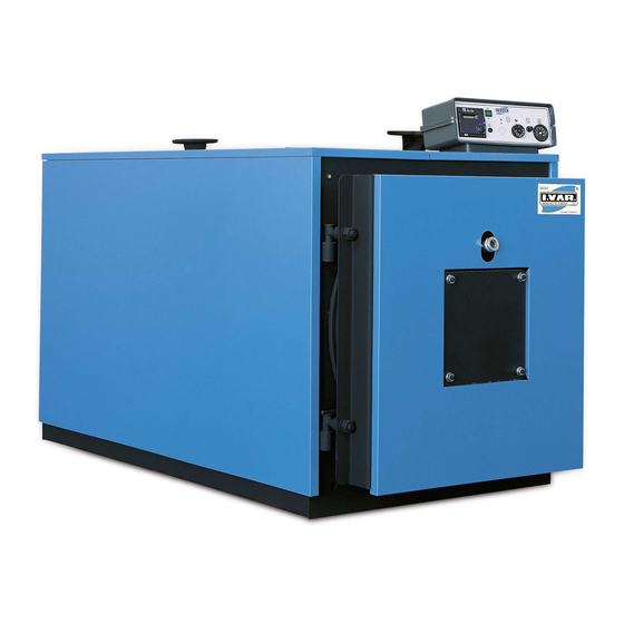
- Page 13 DESCRIPTION OF THE APPLIANCE CHECKS AFTER BOILER CLEANING OPERATIONS The steel boiler from the SUPERAC range is a high performance generator for After performing maintenance and cleaning operations, repeat the preliminary heating systems up to 90°C. When combined with a hot water tank, this start up inspection (see page 23), check the burner calibration and perform a generator can be used also for the production of domestic hot water.
- Page 16 OPENING AND ADJUSTMENT OF THE DOOR The door can be opened from both sides (except for models 2910÷4070). The opening is normally from left to right. To open the door, remove the fixing nuts from the left side. To change the direction of opening of the front door with help of lifting equipment, work as follow: hood the front door to the lifting equipment through the foreseen 2 holes that are in the superior part;...
- Page 18 MODEL S U P E R A C Rated output 104. 151. Furnace thermal output 115. Furnace counterpressure mbar Water side loading loss (∆t 11.8 16.3 mbar 15°C) Boiler water content Max boiler working pressure Min boiler return temperature °C allowed Max boiler temperature °C...
- Page 19 Weight in empty conditions 2100 2350 3450 3850 5200 5800 8000...
-
Page 21: Technical Specifications
It is very important to inspect the boiler/flue fitting seal because of the above TECHNICAL SPECIFICATIONS reasons. Check the pumps correct sense of direction. Check the total standstill of the appliance by turning off the main switch. After all conditions have been satisfied, the burner must be tested at the boiler max. -
Page 24: Identification Elements
IDENTIFICATION ELEMENTS FIRST START UP The appliance can be identified through the TECHNICAL PLATE that After performing the preliminary checks, to power on the boiler it is contains the performing values and identification data. necessary: The plate is applied in the front right upper part. - that the boiler thermostat on the control panel is set between 60 and 90°C, For any servicing and spare part the correct identification of the boiler model according to the type of heating plant;... -
Page 26: Start Up
START UP OPERATIONS PRELIMINARY OPERATIONS PRIOR TO STARTING UP FOR THE FIRST TIME The boiler first start up operation must be carried out by professionally qualified personnel. Later, it will start automatically. Before starting up: The user, for instance, may need to re-start the boiler personally after a long check that the gauges of setting and control instruments have been period of inactivity. -
Page 29: Turning Off
CONTROL PANEL INSTALLATION TURNING OFF The control panel is placed in a box inside the furnace or next to the boiler. In the event of temporary periods of inactivity (week-ends, short trips, etc.) Voltage 220 V - 50 Hz. with no danger of frost, follow the procedure below: Open the instrument panel by turning of the self-threading screws. - Page 31 Position the superior covers (4) (5) on the boiler. PRODUCT RECEIPT Before joining them together, prepare the control panel (6) as specified below and fix it on the right superior panel as follows: extend the feeler capillaries, Up to mod. SUPERAC 1045: make then pass through the cover hole and insert them in the wells located - boiler body without insulation (the box of the electric board, the near the delivery tube.
-
Page 33: Dimensions
The fuel connections to the burner must be positioned in order to permit complete opening of the boiler door with the burner fitted. COVER ASSEMBLING (only SUPERAC 93 ÷ 1045) WARNING: carry out the cover assembling after finished the installation works. -
Page 36: Installation
FUEL SUPPLY The fuel supply line must comply with current regulations and be laid by professionally qualified personnel.. Before installation, you are advised to thoroughly clean the inside of all the fuel supply pipes in order to remove any debris that may affect correct operation of the boiler. -
Page 37: Installation Premises
INSTALLATION INSTALLATION PREMISES The boiler must be installed in a room that complies with the provisions and minimum distances provided for by the current regulations and is provided BOILER with suitably sized air vents. The flat surface of the boiler must be positioned horizontally. The flat surface should be raised from the floor. -
Page 40: Hydraulic Connection
You are advised to insulate the heating system pipes to avoid heat dispersion HYDRAULIC CONNECTION resulting in increased fuel consumption and environmental pollution. The choice and installation of the system components is the responsibility of the installer who must operate in accordance with correct working practice and ELECTRICAL SYSTEM the current legislation. - Page 41 MODEL S U P E R A C 1110 1110 1360 1405 1405 1655 1655 1905 Dimensions 1010 1010 1010 1260 1260 1510 r / m 2“ 2“ 2“ Fittings 1”1/ 1”1/ 1”1/ 1”1/ 1”1/ 1”1/ 1”1/ 1”1/ ¾” ¾” ¾”...
- Page 42 Fittings 1”1/2 1”1/2 1”1/2 1”1/2 1”1/2 1”1/2 1”1/2 ∅...
Need help?
Do you have a question about the SUPERAC 93 and is the answer not in the manual?
Questions and answers