Chapters
Table of Contents

Related Manuals for LG NP5550B


Summary of Contents for LG NP5550B
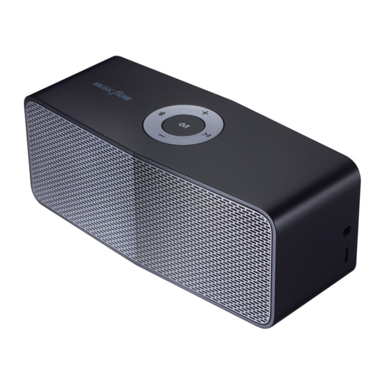
- Page 1 Internal Use Only Website http://biz.lgservice.com Portable Bluetooth Speaker SERVICE MANUAL MODEL: NP5550B/ NP5550W CAUTION BEFORE SERVICING THE UNIT, READ THE “SAFETY PRECAUTIONS” IN THIS MANUAL. P/NO : AFN77272381 SEPTEMBER, 2015...
- Page 2 CONTENTS SECTION 1 ..GENERAL SECTION 2 ..CABINET & MAIN CHASSIS SECTION 3 ..ELECTRICAL SECTION 4 ..REPLACEMENT PARTS LIST...
- Page 3 SECTION 1 GENERAL CONTENTS ESD PRECAUTIONS ............................1-3 HIDDEN KEY MODE ............................1-4 PROGRAM UPDATE GUIDE ..........................1-5 SPECIFICATIONS ............................. 1-6...
-
Page 4: Esd Precautions
ESD PRECAUTIONS Electrostatically Sensitive Devices (ESD) Some semiconductor (solid state) devices can be damaged easily by static electricity. Such components commonly are called Electrostatically Sensitive Devices (ESD). Examples of typical ESD devices are integrated circuits and some field-effect transistors and semiconductor chip components. The following techniques should be used to help reduce the incidence of component damage caused by static electricity. -
Page 5: Hidden Key Mode
HIDDEN KEY MODE Hidden Key Description Dual Play Master “Bluetooth” + “Volume Up” key for 2 seconds Dual Play Slave “Bluetooth” + “Volume Down” key for 2 seconds Hardware PMC Mode Entry Push long time the "Power" key TV Mode Entry “Bluetooth”... -
Page 6: Program Update Guide
2) Hidden mode set up : “Volume Up” + “Power” key for 3 seconds. (you can check beep sound) 3) Connect bluetooth and run ‘LG Audio Bluetooth’ App. (you may download on “Google Play store”) 4) FOTA Update : ① Setting menu on the App ② Check version information ③ FOTA update (check FOTA guide in below) Step 2. -
Page 7: Specifications
SPECIFICATIONS Power Supply 1.8 A (AC Adapter) Built-in rechargeable battery Power consumption Dimensions (W x H x D) Approx. 153 mm x 58 mm x 59.5 mm Net Weight Approx. 0.47 kg Operating Temperature 5 °C to 35 °C Operating Humidity 5 % to 60 % External Connector ø... -
Page 8: Table Of Contents
SECTION 2 CABINET & MAIN CHASSIS CONTENTS DISASSEMBLY INSTRUCTIONS ........................2-2 1. HOW TO DISASSEMBLE THE GRILLE ....................2-2 ASSEMBLY INSTRUCTIONS ........................... 2-4 1. HOW TO ASSEMBLE THE GRILLE ......................2-4 EXPLODED VIEWS ............................2-7 1. CABINET AND MAIN FRAME SECTION ....................2-7 2. -
Page 9: Disassembly Instructions
DISASSEMBLY INSTRUCTIONS 1. HOW TO DISASSEMBLE THE GRILLE 1) Set is placed on top of soft sheet so as not to damage. Figure 1 2) After remove foot on the bottom, remove screw of the rear of Bottom screw using a phillips screwdriver. Figure 2... - Page 10 3) Using a thin fl at tool (ex. A fl athead screwdriver), push the grille to outside. Figure 3 4) Disassemble grille after holding grille. Figure 4...
-
Page 11: Assembly Instructions
ASSEMBLY INSTRUCTIONS 1. HOW TO ASSEMBLE THE GRILLE 1) Assemble the hook of set to meet with hook of grille. Figure 1 2) After the hook of set to meet with hook of grille, assemble in the direction of the arrow. Figure 2... - Page 12 4) Assemble the rear screw 2 EA using a phillips screwdriver. Figure 3...
-
Page 14: Exploded Views
EXPLODED VIEWS 1. CABINET AND MAIN FRAME SECTION NOTES) THE EXCLAMATION POINT WITHIN AN EQUILATERAL TRIANGLE IS INTENDED TO ALERT THE SERVICE PERSONNEL TO THE PRESENCE OF IMPORTANT SAFETY INFORMATION IN SERVICE LITERATURE. 260A 261A CABLE1 BATCNT BATTERY CABLE3 CABLE2... -
Page 15: Packing Accessory Section
2. PACKING ACCESSORY SECTION 820 USB Data cable 801 Owner’s manual 803A Packing 803 Packing 802B Owner’s manual box 802A Accessory box 802 Box... - Page 16 SECTION 3 ELECTRICAL CONTENTS ONE POINT REPAIR GUIDE ..........................3-2 1. NO POWER PROBLEM ......................... 3-2 2. NO SOUND IN PORTABLE MODE ......................3-3 3. NO SOUND IN BLUETOOTH MODE ..................... 3-4 4. NO CHARGING BATTERY ........................3-5 ELECTRICAL TROUBLESHOOTING GUIDE ....................3-6 1.
-
Page 17: One Point Repair Guide
ONE POINT REPAIR GUIDE 1. NO POWER PROBLEM No power problem occurs when you power on the unit. 1-1. Solution Check and replace IC903 on main board. 1-2. How to troubleshoot (Countermeasure) 1) Check battery is enough or not. 2) Check 3V3 (FB901). ... -
Page 18: Sound In Portable Mode
ONE POINT REPAIR GUIDE 2. NO SOUND IN PORTABLE MODE No sound problem occurs in portable mode. 2-1. Solution Check and replace IC500 on main board. 2-2. How to troubleshoot (Countermeasure) 1) Check solder of JK300. 2) Check if signal enters pin2 and pin7 of IC500. 3) Check if signal comes out from pin63 ~ 66 of IC500. -
Page 19: Sound In Bluetooth Mode
ONE POINT REPAIR GUIDE 3. NO SOUND IN BLUETOOTH MODE No power problem occurs when you power on the unit. 3-1. Solution Check and replace IC500 on main board. 3-2. How to troubleshoot (Countermeasure) 1) Check if bluetooth is in pairing state with your device. 2) Check if signal comes out from pin63 ~ 66 of IC500. -
Page 20: Charging Battery
ONE POINT REPAIR GUIDE 4. NO CHARGING BATTERY Battery is not charged. 4-1. Solution Check and replace IC901 on main board. 4-2. How to troubleshoot (Countermeasure) 1) Check voltage of battery. 2) Check pin3 of IC901. (It should be 4.5 V ~ 5 V) 3) Check pin6 of IC901. -
Page 21: Electrical Troubleshooting Guide
ELECTRICAL TROUBLESHOOTING GUIDE 1. POWER DSP/ AMP Power DSP Check connection of CN901. Connect CN901. Is voltage of the battery Charge the battery. above 3.3 V? (CN901) Is voltage of SYS_PWR Replace IC901. 3.3 V ~ 4.2 V? (IC903 pin5) 3V3 is voltage of 3.3 V? (FB901) Replace IC903. -
Page 22: Amp (Portable Mode)
ELECTRICAL TROUBLESHOOTING GUIDE 2. AMP (PORTABLE MODE) No sound Check connection of CN700. Connect CN700. Does 5 V or 9 V flow IC700. Replace IC902. (check pin12 ~ 14)? No sound in portable mode? Check if signal enters IC500. 1) Check the soldering JK300. (check pin2, 7) 2) Replace portable cable. -
Page 23: Key/ Led
ELECTRICAL TROUBLESHOOTING GUIDE 3. KEY/ LED KEY/ LED Is input voltage 3.3 VA? (FB901) Check power DSP. (replace IC903) Is control high? (KEY: pin4, 6, 14, 15 of CN200) Check power DSP. (replace IC500) (LED: pin8, 10, 12, 16, 18 of CN200) -
Page 24: Charging Battery
ELECTRICAL TROUBLESHOOTING GUIDE 4. CHARGING BATTERY Charging battery “Amber” LED of “Power” key blink? Charging battery. Check the connection of adapter cable. Connect adapter cable. 5 V is voltage of 4.2 V ~ 5 V? Check adapter. (IC901 pin18,19) Is voltage of DRV5V Replace IC901. -
Page 25: Waveforms Of Major Check Point
WAVEFORMS OF MAJOR CHECK POINT 1. CHARGER IC 1) R904 : I2C_SDA (Green) 2) R905 : I2C_SCL (Yellow) Fig1. Charger IC I2C waveform 3-10... -
Page 26: Wiring Diagram
WIRING DIAGRAM 4P, 2.5mm BATTERY AG, SMD (EAG63189901) JUCNTION 6P, 1.25mm AG, SMD Locking KEY/ LED (6630V90141E) BATTERY 20P, 0.5mm CN101 ST, SMD B to B (EAG64673501) CN200 4P, 1.25mm CN500 CN901 ST, Locking, SMD (EAG58732903) 20P, 0.5mm 6P, 1.25mm ST, SMD B to B ST, SMD Locking (EAG64673601) -
Page 27: Block Diagrams
BLOCK DIAGRAMS 1. SYSTEM BLOCK DIAGRAM 3.5 V ~ 4.3 V BAT+ BATTERY 3.3 V ~ 4.3 V VBUS 3.7 V 2100 mAh 3.3 V ~ 4.3 V Charger IC DRIVE BQ24262 PVCC (Q900) (IC901) DC 5 V 9 V / 5 V SYSTEM BAT+SYS SYS_V... -
Page 28: Power Block Diagram
2. POWER BLOCK DIAGRAM BATTERY 3.5 V ~ 4.3 V 3.7 V 2100 mAh 3.3 V ~ 4.3 V Charger IC PVCC Boost Block PVCC BQ24262 DC 5 V COIL 3.3 µH 3.3 µH TPS61088 mUSB 3.3 V 5 V 5 mA LED x 2 Buck/ Boost 3.3 µH... -
Page 29: Circuit Diagrams
CIRCUIT DIAGRAMS 1. MAIN - AMP CIRCUIT DIAGRAM EAX66583001_Rev1.7(16) 2015. 08. 13 3-17 3-18... -
Page 30: Main - Power/ Charger Circuit Diagram
2. MAIN - POWER/ CHARGER CIRCUIT DIAGRAM : WAVEFORM NUMBER POWER/ CHARGER EAX66583001_Rev1.7(16) 2015. 08. 13 3-19 3-20... -
Page 31: Key/ Led Circuit Diagram
3. KEY/ LED CIRCUIT DIAGRAM KEY/ LED EAX66784101_Rev1.7(16) 2015. 08. 13 3-21 3-22... -
Page 32: I/O Jack Circuit Diagram
4. I/O JACK CIRCUIT DIAGRAM I/O JACK EAX66743201_Rev1.7(16)_IO 2015. 08. 13 3-23 3-24... -
Page 33: Battery Jucntion Circuit Diagram
5. BATTERY JUCNTION CIRCUIT DIAGRAM BATTERY JUCNTION EAX66732401_Rev1.6(14) 2015. 08. 13 3-25 3-26... -
Page 34: Circuit Voltage Chart
CIRCUIT VOLTAGE CHART IC Sym IC Name/ Type Vcc/ Vdd WB1NP6 HCI. (CSR8670) Spec: TYPE: MODULE (70 P) VDD: - 0.4 ~ 3.6 V IC500 Module VENDER: MCS Logic Measure: VDD: 22, 38, 69 P VDD: + 3.35 V 337S3959 Clsas Spec: 6 i-pod 2.0 C Vcc : 1.62 ~ 5.5 V... -
Page 35: Printed Circuit Board Diagrams
PRINTED CIRCUIT BOARD DIAGRAMS 1. MAIN P. C. BOARD (TOP VIEW) (BOTTOM VIEW) 3-29 3-30... -
Page 36: Key/ Led P. C. Board
2. KEY/ LED P. C. BOARD (TOP VIEW) (BOTTOM VIEW) 3. I/O JACK P. C. BOARD (TOP VIEW) (BOTTOM VIEW) 4. BATTERY JUCNTION P. C. BOARD (TOP VIEW) (BOTTOM VIEW) 3-31 3-32... - Page 37 3-33 3-34...
Need help?
Do you have a question about the NP5550B and is the answer not in the manual?
Questions and answers