Advertisement
Advertisement
Table of Contents

Related Manuals for RoboMaster C610

Summary of Contents for RoboMaster C610
- Page 1 RoboMaster C610 Brushless DC Motor Speed Controller User Guide v1.0 2019.03...
- Page 2 Failure to do so may reduce the product service life or even lead to permanent damage. Introduction Using a 32-bit motor driver chip and field-oriented control (FOC), the RoboMaster C610 Brushless DC Motor Speed Controller enables precise control over motor torque. It is compatible with the M2006 P36 Brushless DC Gear Motor* to create a complete propulsion system.
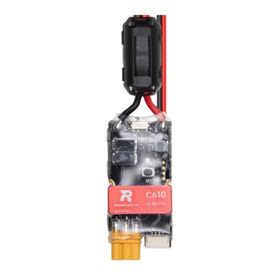
- Page 3 In the Box C610 Speed Controller × 1 Heat-shrink Tubing × 1 Overview C610 Brushless DC Motor Speed Controller 1. Power Cable Connects to a 24 V power supply to provide power for the speed controller. 2. 3-Phase Power Cable Connects to the 3-phase cable of the M2006 motor.
-
Page 4: Connecting The Speed Controller
Connects to a USB-to-serial converter by soldering. Connect the USB-to-serial converter to a computer to configure the parameters or update the firmware of the speed controller via RoboMaster Assistant. When the CAN bus command control is in use, the information of the position and rotational speed of the rotor can be acquired. - Page 5 USB-to-serial converter via RoboMaster Assistant. The voltage of the USB-to-serial converter must be 3.3 V. 1. Download RoboMaster Assistant from the official RoboMaster website. https://www.robomaster.com/products/components/assistant 2. Connect the speed controller to the Takyon Updater by soldering, and connect the Takyon Updater to a computer.
-
Page 6: Status Led Description
3. Connect the speed controller to a power supply. 4. Launch RoboMaster Assistant. 5. Click Settings to adjust parameters. 6. Click Firmware Update and select the version you want for the speed controller. RoboMaster Assistant will automatically download and update the firmware. Status LED Description The status LED is used to indicate the operational status of the speed controller. - Page 7 Using the Set Button 1. Separate ID Setting Follow the steps below to assign a unique ID to each speed controller (from 1-8): a. Press the Set button once to activate separate ID assignment mode for the speed controller. Once the speed controller is in ID assignment mode, the status LED is powered off. b.
-
Page 8: Can Communication Protocol
CAN Communication Protocol 1. Speed Controller Receiving Message Format The two identifiers (0×200 and 0×1FF) control the current output of each of the four speed controllers by ID. The controllable current range is -10000 ~ 0 ~ 10000. The corresponding speed controller output torque current range is -10 ~ 0 ~ 10 A. -
Page 9: Specifications
DATA[3] DATA[7] Null lower order byte (8 bits) Sending frequency: 1 KHz by default (can be changed using RoboMaster Assistant) Rotor mechanical angle value range: 0 ~ 8191 (corresponding mechanical angle range: 0 ~ 360°) Rotor speed value unit: rpm Performance Diagram (Using M2006 Motor) η(%) n(rpm) - Page 10 WWW.ROBOMASTER.COM are trademarks of DJI. Copyright © 2019 DJI All Rights Reserved.
Need help?
Do you have a question about the C610 and is the answer not in the manual?
Questions and answers