Table of Contents
Advertisement
Revision Number: Initial Issue
Prepared by: Edmund Ceurstemont
Authorised by: Darryl Newborough
Issue Date: 20/12/2010
Commercial in Confidence
This document contains Sonardyne
Technical information and is issued
Commercial in Confidence.
The contents of this document must not
be divulged to any third party without
Sonardyne's written permission
Issuing Office
Sonardyne International Limited
Blackbushe Business Park
Yateley, Hampshire
GU46 6GD United Kingdom
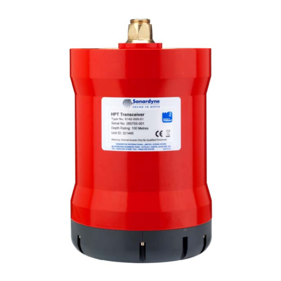
Type 8142-000-01/02 USBL Transceivers
Type 8182-000-01 Modem/transceiver
Sonardyne Wideband2®
6 Generation (6G®)
T. +44 (0) 1252 872288
F. +44 (0) 1252 876100
E.
support@sonardyne.com
Sonardyne International
Ltd.
UM-8142/8182
User Manual for:
Advertisement
Chapters
Table of Contents

Related Manuals for Sonardyne 8142-000-01


Summary of Contents for Sonardyne 8142-000-01
- Page 1 UM-8142/8182 User Manual for: Revision Number: Initial Issue Type 8142-000-01/02 USBL Transceivers Prepared by: Edmund Ceurstemont Authorised by: Darryl Newborough Type 8182-000-01 Modem/transceiver Issue Date: 20/12/2010 Commercial in Confidence This document contains Sonardyne Technical information and is issued Commercial in Confidence.
-
Page 2: Preliminaries
11.3 Precautions (Instrument known or suspected of being Pressurised) 12 – Instrument Load Bearing Capacity 13 – Floatation Equipment Head Office T. +44 (0) 1252 872288 Sonardyne International Limited F. +44 (0) 1252 876100 Blackbushe Business Park, E. support@sonardyne.com Yateley, Hampshire, www.sonardyne.com... - Page 3 4.2 Dynamic Positioning 5 - LUSBL 5.1 Dynamic Positioning 5.2 Underwater Positioning 5.3 Marine Riser Angle Monitoring Technical Data 1 – 8142-000-01 Transceiver and 8182-000-01 Transceiver 1.1 Mechanical 1.2 Electrical 1.3 Acoustics 1.4 Environmental 2 – 8142-000-02 Transceiver 2.1 Mechanical 2.2 Electrical...
- Page 4 Initial Issue Page 3of 5 Issue Date 25/06/2010 User Manual: 8142/8182 Transceivers Table of Contents 0-1 Maintenance and Storage 1 – 8142 Transceivers Clean, Examine and Store 1.1 Tools 1.2 Consumable Materials 1.3 Preparation 1.4 Clean and Examine the Transceiver 1.5 Storage 1.6 Post Task Procedures 2 –...
- Page 5 2 – Recommended Spares 2.1 Transceiver 8142-000-001/2 2.2 Assemblies 2.3 Cables Drawings 1 – AGP Tail Stripping Detail 2 – 8 Pin Lemo to Flylead 3 – HPT Outline – 8142-000-01 4 – Serial I/O cable Assembly 5 – HPT Outline – 8142-000-02...
- Page 6 Initial Issue Page 5of 5 Issue Date 25/06/2010 User Manual: 8142/8182 Transceivers Table of Contents 0-1 Deployment 1 – 8142 transceiver Deployment 1.1 Preparation 1.2 Deployment From Ship Equipment Log Book 1 – Deployment and Recovery 2 – Repairs 3 - Servicing 4 –...
- Page 7 CUSTOMER CHANGE REQUEST FORM 0-2 Use this form to tell Sonardyne Int Ltd of any errors or omissions that you find when you use this manual. Your request will be acknowledged and Sonardyne Int Ltd will inform you of any action to be taken.
- Page 8 RECORD OF REVISION 0-3 Rev No. Description Page/ Date Inserted By Date Initial Issue Complete Issue Sonardyne Int Ltd 20/12/2010 Head Office T. +44 (0) 1252 872288 Sonardyne International Limited F. +44 (0) 1252 876100 Blackbushe Business Park, E. support@sonardyne.com Yateley, Hampshire, www.sonardyne.com...
-
Page 9: Introduction
11.3 PRECAUTIONS (INSTRUMENT KNOWN OR SUSPECTED TO BE PRESSURISED) INSTRUMENT LOAD BEARING CAPABILITY FLOATATION EQUIPMENT Head Office T. +44 (0) 1252 872288 Sonardyne International Limited F. +44 (0) 1252 876100 Blackbushe Business Park, E. support@sonardyne.com Yateley, Hampshire, www.sonardyne.com GU46 6GD, UK... -
Page 10: Table Of Contents
Section: Introduction 0-4 Revision: 00 GENERAL This User Manual is issued by Sonardyne International Limited. This User Manual contains all the information necessary to operate and maintain the equipment in an operational environment. This User Manual contains the technical data, operating instructions, maintenance schedules, maintenance procedures, spares information and all applicable drawings and parts lists. - Page 11 / instructions correctly, you can cause damage to the equipment, its assemblies, components or parts. Only the procedures and instructions given in this User Manual have the approval of Sonardyne International Limited. If a necessary procedure or instruction is not given in this User Manual, before you continue you must contact Sonardyne International Limited.
- Page 12 Any claim under this warranty must be lodged in writing with Sonardyne within twelve months and the part or parts returned to Sonardyne within thirteen months of the commencement of the warranty. The warranty will commence upon the commissioning or putting into service of the equipment or one month from shipment from Sonardyne, whichever is the sooner.
-
Page 13: Technical And Functional Description
You must keep this User Manual clean, readable and complete. You must tell Sonardyne International Limited of any errors that you find when you use this User Manual. The content of each section of the User Manual is described in the following paragraphs: Technical and Functional Description Para.3.1... - Page 14 User Manual: Generic Section Page 6 of 21 Section: Introduction 0-4 Revision: 00 Technical and Functional Description Description of the assemblies that make up the equipment and how they operate. Technical data All the equipment Specifications included in the User Manual. Operating instructions This section gives the information necessary to operate the equipment.
- Page 15 GLOSSARY OF TERMS NOTE: The terms that follow are general and are not specific to this User Manual. NOTE: The table that follows contains User Operator Terms, Sonardyne Systems, Signal Processing and Communication Terms and General Terms. User Operator Terms Term...
- Page 16 Acoustic Signal Information carried by sound pressure waves through water. The Sonardyne acoustic signal has a finite length Common Reply Signal (CRS) A reply signal common to a complete family of addressed transponders.
- Page 17 User Manual: Generic Section Page 9 of 21 Section: Introduction 0-4 Revision: 00 User Operator Terms Term Definition Digital Signal Processing (DSP) The representation of signals by a sequence of numbers or symbols and the processing of these signals. DSP includes subfields like: audio and speech signal processing, sonar and radar signal processing, sensor array processing.
- Page 18 Unit Identification Number (UID) Each product produced by Sonardyne Int Ltd contains a unique 24bit address. It is denoted by 6 hexadecimal characters. Wideband Test Terminal (WTT) PC software for testing 6G transponders and transceivers.
- Page 19 User Manual: Generic Section Page 11 of 21 Section: Introduction 0-4 Revision: 00 Sonardyne Systems Term Definition Long-Base-Line (LBL) System A system where two or more transponders are on the seabed. The positions of the transponders are established by a calibration process in a seabed frame.
- Page 20 User Manual: Generic Section Page 12 of 21 Section: Introduction 0-4 Revision: 00 Sonardyne Systems Term Definition Sound Speed Profile At different depths the temperature, salinity and pressure vary, so the local sound speed varies. Depth cannot be measured directly. So pressure measurements are taken, and the depth calculated, using knowledge of density and local gravity.
- Page 21 User Manual: Generic Section Page 13 of 21 Section: Introduction 0-4 Revision: 00 Sonardyne Systems Term Definition Vertical Reference Gyroscope (VRG) A gyroscopically stabilised VRU. Vertical Reference Unit (VRU) Measures the instantaneous roll and pitch of a vessel Vessel A body floating in the sea with at least part of it penetrating the surface.
- Page 22 User Manual: Generic Section Page 14 of 21 Section: Introduction 0-4 Revision: 00 General Terms Term Definition Access A procedure to get to an assembly, component or part to do a specific task Adjust To change the position of a part to get a specified setting Align To make two or more parts come together Applicable...
- Page 23 User Manual: Generic Section Page 15 of 21 Section: Introduction 0-4 Revision: 00 General Terms Term Definition Overhaul Maintenance operation to completely return an assembly, sub- assembly or component to a serviceable condition Pack The procedure required to prepare equipment for storage and or transportation Preserve To prepare equipment for storage and transportation that...
- Page 24 User Manual: Generic Section Page 16 of 21 Section: Introduction 0-4 Revision: 00 General Terms Abbreviation Definition AC/DC Alternating Current / Direct Current Ampere-Hours As Required Assy Assembly Auxiliary Baud Blow Out Preventer bits per seconds British Standard Cg / COG Centre of Gravity Centimetre Centre of Rotation...
- Page 25 User Manual: Generic Section Page 17 of 21 Section: Introduction 0-4 Revision: 00 General Terms Abbreviation Definition Kilo Newton Pound lbf in. Pounds force inches lbf/in² Pounds force / square inch Metre Metres per second Max. Maximum µs Microsecond Milligram Min.
- Page 26 User Manual: Generic Section Page 18 of 21 Section: Introduction 0-4 Revision: 00 General Terms Abbreviation Definition tonne Volt Watt hour < Less than ≤ Less than or equal to > More than ≥ More than or equal to GENERAL SAFETY PRECAUTIONS The general safety precautions that follow are not specific to any installation or equipment.
- Page 27 User Manual: Generic Section Page 19 of 21 Section: Introduction 0-4 Revision: 00 When you do a procedure or task you must make sure that: You wear all applicable Personal Protective Equipment (PPE). You do not cause injury to you or other persons. All applicable cranes and lifting equipment are serviceable and calibrated and have the correct Safe Working Load (SWL) for the task.
- Page 28 User Manual: Generic Section Page 20 of 21 Section: Introduction 0-4 Revision: 00 DISMANTLING SUB-SEA EQUIPMENT All sub-sea equipment fitted with pressure housings are subject to a vast range of externally applied pressures and may have an internal pressure rise if a leak occurs or the unit’s battery destructs. Internal pressure is dangerous situation and all applicable safety measures must be enforced.
- Page 29 It is the operator’s responsibility to make sure the condition of the equipment and a safe lifting method is being used for any operation. Sonardyne’s range of Oceanographic Release Transponders is designed specifically for in-line lifting operations. Appropriate shackles must be used in release systems to ensure freedom from corrosion. It is important to note that instruments, their release mechanisms and shackles form part of an integrated and complete system.
- Page 30 TABLE OF CONTENTS 0-1 CUSTOMER CHANGE REQUEST FORM (CCRF) 0-2 RECORD OF REVISIONS 0-3 INTRODUCTION 0-4 Head Office T. +44 (0) 1252 872288 Sonardyne International Limited F. +44 (0) 1252 876100 Blackbushe Business Park, E. support@sonardyne.com Yateley, Hampshire, www.sonardyne.com GU46 6GD, UK...
- Page 31 TYPE 8142 USBL TRANSCEIVERS AND TYPE 8182 TRANSCEIVERS Contents GENERAL SYSTEM DESCRIPTION TYPE 8142 TRANSCEIVER TYPE 8182 TRANSCEIVER ACOUSTIC PROCESSING PRINCIPLES POSITIONING SONARDYNE WIDEBAND®2 SIGNALS DATA EXCHANGE USBL ROV/TOW FISH TRACKING DYNAMIC POSITIONING LUSBL DYNAMIC POSITIONING UNDERWATER POSITIONING MARINE RISER ANGLE MONITORING Head Office T.
-
Page 32: General
USBL, Long-Ultra-Short-Base-Line (LUSBL) Marine Riser Angle Monitoring System (MRAMS) and data retrieval systems. The Sonardyne Wideband®2 Type 8142-000-01 6G® transceiver is the standard USBL system. It has a standard array and is used for navigation and data retrieval. - Page 33 User Manual: 8142/8182 Transceivers 02 Technical and Functional The Sonardyne Wideband®2 Type 8182-000-01 6G® series of units operate as high data rate modems only. They have almost the same functionality as the Type 8142 series but DO NOT present any bearing information.
- Page 34 Initial issue Page 4of 10 Issue Date 25/06/2010 User Manual: 8142/8182 Transceivers 02 Technical and Functional The processor within the transceiver runs a program stored in memory. This firmware controls all the functions of the unit. An underwater connector is provided in the top of the housing for connection with the interface cable. Nominally 48V power is supplied to the unit using a single pair of conductors.
- Page 35 Initial issue Page 5of 10 Issue Date 25/06/2010 User Manual: 8142/8182 Transceivers 02 Technical and Functional DATA FUSION ENGINE (DFE) DYNAMIC POSITIONING (DP) SYSTEM DIFFERENTIAL GLOBAL POSITIONING SYSTEM (DGPS) USBL/LUSBL ACOUSTIC TRANSCEIVER VERTICAL REFERENCE UNIT (V RU)/ GYRO COMPASS ACOUS TRANSPONDERS Figure 3: Type 8142 USBL / LUSBL System...
- Page 36 Initial issue Page 6of 10 Issue Date 25/06/2010 User Manual: 8142/8182 Transceivers 02 Technical and Functional DATA FUSION ENGINE (DFE) 8182 ACOUSTIC TRANSCEIVER/MODEM High data rate acoustic link, up to 10kbps ACOUSTIC TRANSPONDER Figure 4: Type 8182 Modem System...
-
Page 37: System Description
Initial issue Page 7of 10 Issue Date 25/06/2010 User Manual: 8142/8182 Transceivers 02 Technical and Functional SYSTEM DESCRIPTION The equipment used in the L/USBL system is as follows (Figure 3: Type 8142 USBL / LUSBL System): Optional output to DP System Gyro compass DGPS Monitor/Keypad unit... -
Page 38: Type 8182 Transceiver
Ref: Section 13 Acoustic processing principles POSITIONING Positioning involves an acoustic cycle. The transceiver sends a Sonardyne Wideband®2 signal to the transponder. This activates the transponder which sends back a Sonardyne Wideband®2 signal to the transceiver. The transceiver will process the information received from the transponder as follows:... -
Page 39: Sonardyne Wideband®2 Signals
SONARDYNE WIDEBAND®2 SIGNALS There are more than 600 Sonardyne Wideband®2 signals. The different signals means the system can be adjusted to various environmental conditions e.g. deep or shallow water and allow accurate Doppler estimates of the target being tracked. -
Page 40: Lusbl
Initial issue Page 10of 10 Issue Date 25/06/2010 User Manual: 8142/8182 Transceivers 02 Technical and Functional LUSBL The transceiver can be used in a LUSBL configuration to provide a higher degree of accuracy in DP applications. DYNAMIC POSITIONING For the DP application to function, with LUSBL, an array of transponders is placed on the seabed and the position of the transponders or array in the vessel frame is reported to the DP control system. - Page 41 Initial Issue Page 1of 5 Issue Date 25/06/2010 User Manual: 8142/8182 Transceivers 03 Technical Data 03 TECHNICAL DATA TYPE 8142 USBL TRANSCEIVERS AND TYPE 8182 TRANSCEIVERS Contents 8142-000-01 TRANSCEIVER AND 8182-000-01 TRANSCEIVER MECHANICAL ELECTRICAL ACOUSTIC ENVIRONMENTAL 8142-000-02 TRANSCEIVER MECHANICAL ELECTRICAL ACOUSTIC...
-
Page 42: 8142-000-01 Transceiver And 8182-000-01 Transceiver
Initial Issue Page 2of 5 Issue Date 25/06/2010 User Manual: 8142/8182 Transceivers 03 Technical Data 8142-000-01 TRANSCEIVER AND 8182-000-01 TRANSCEIVER The information is the same for both transceiver series unless otherwise stated. MECHANICAL Parameter Specification Diameter (max) 225mm (8.85ins) Overall length 370mm (14.57ins) -
Page 43: Acoustic
Initial Issue Page 3of 5 Issue Date 25/06/2010 User Manual: 8142/8182 Transceivers 03 Technical Data ACOUSTIC Parameter Specification Transmitting: Directivity Index 8 dB approx Source Level 169 to 199 dB ref:1Pa@ 1 m Receiving: Operating Envelope ±80° (160 deg) min Sensitivity Threshold 80 dB ref 1 micro pascal Repeatability (8142 ONLY) -
Page 44: 8142-000-02 Transceiver
Initial Issue Page 4of 5 Issue Date 25/06/2010 User Manual: 8142/8182 Transceivers 03 Technical Data 8142-000-02 TRANSCEIVER MECHANICAL Parameter Specification Diameter (max) 310mm (12.2ins) Overall length 433mm (17ins) Note: An additional 180mm (7ins) should be allowed for flange and connector to fit onto a sea chest. -
Page 45: Acoustic
Initial Issue Page 5of 5 Issue Date 25/06/2010 User Manual: 8142/8182 Transceivers 03 Technical Data ACOUSTIC Parameter Specification Transmitting: Directivity Index 8 dB approx Source Level 169 to 199 dB ref: 1Pa@ 1 m Receiving: Operating Envelope ±80° (160 deg) min @ 24kHz to 48° min @ 32kHz Sensitivity Threshold 80 dB ref 1 micro pascal Repeatability... -
Page 46: Head Office
TYPE 8142 USBL TRANSCEIVERS AND TYPE 8182 TRANSCEIVERS Contents 8142 TRANSCEIVERS AND 8182 TRANSCEIVERS OPERATING INSTRUCTIONS Head Office T. +44 (0) 1252 872288 Sonardyne International Limited F. +44 (0) 1252 876100 Blackbushe Business Park, E. support@sonardyne.com Yateley, Hampshire, www.sonardyne.com GU46 6GD, UK... - Page 47 8142 TRANSCEIVERS AND 8182 TRANSCEIVERS OPERATING INSTRUCTIONS If the following transceivers have been installed: Type 8142-000-01 Type 8142-000-02 The system is monitored and controlled by the Marksman Ranger 2 software package. For all operating instructions (Ref to the Marksman Ranger 2 operating Manual).
- Page 48 CLEAN AND EXAMINE THE TRANSCEIVER STORAGE POST TASK PROCEDURES RECOMMENDED LUBRICANTS MAINTENANCE CODES AND SCHEDULE Head Office T. +44 (0) 1252 872288 Sonardyne International Limited F. +44 (0) 1252 876100 Blackbushe Business Park, E. support@sonardyne.com Yateley, Hampshire, www.sonardyne.com GU46 6GD, UK...
- Page 49 Initial Issue Page 2of 3 Issue Date 25/06/2010 User Manual: 8142/8182 Transceivers 05 Maintenance and Storage 8142 AND 8182 TRANSCEIVERS CLEAN, EXAMINE AND STORE 1.1 TOOLS Part Number Description 1.2 CONSUMABLE MATERIALS Specification Description Local Supply Fresh water Local Supply Clean Lint Free Cloths Local Supply Soft Abrasive Pads (Scotch bright)
- Page 50 Initial Issue Page 3of 3 Issue Date 25/06/2010 User Manual: 8142/8182 Transceivers 05 Maintenance and Storage 1.5 STORAGE Dry transceiver with clean lint free cloths. Blank off all connections. Clean the inside of the protective boot. Put the boot on the transceiver. Store the transceiver in the original transit case or an applicable container in a dry secure area.
- Page 51 NO COMMNUICATION FROM TRANSCEIVER CHECK THE WIRING AND THE POWER CHECK AGP CONNECTOR CHECK CONTINUITY OF RS485 CONNECTION Head Office T. +44 (0) 1252 872288 Sonardyne International Limited F. +44 (0) 1252 876100 Blackbushe Business Park, E. support@sonardyne.com Yateley, Hampshire, www.sonardyne.com...
- Page 52 Initial Issue Page 2of 3 Issue Date 25/06/2010 User Manual: 8142/8182 Transceivers 06 Fault Finding NO COMMNUICATION FROM TRANSCEIVER CHECK THE WIRING AND THE POWER Check the LED’s on the Navigation Sensor Hub (NSH) to confirm power is available to the transceiver.
- Page 53 Initial Issue Page 3of 3 Issue Date 25/06/2010 User Manual: 8142/8182 Transceivers 06 Fault Finding NSH (Rear View) RS 485 A Transceiver A Junction Box (ship supply) Type 7784-159 CPN 820-3650 Black Yellow White Blue Type 8020-061 Orange CPN 820-6459 Green Screen Violet...
- Page 54 EQUIPMENT WEIGHTS PREPARATION THE METHOD, FOR REMOVING THE TRANSCEIVER FROM THROUGH DECK POLE OR OVER-SIDE MOUNT: Head Office T. +44 (0) 1252 872288 Sonardyne International Limited F. +44 (0) 1252 876100 Blackbushe Business Park, E. support@sonardyne.com Yateley, Hampshire, www.sonardyne.com GU46 6GD, UK...
- Page 55 Initial Issue Page 2of 5 Issue Date 25/06/2010 User Manual: 8142/8182 Transceivers 07 Removal REMOVAL TRANSCEIVERS 8142-000-001/2 AND TYPE 8182 TRANSCEIVERS TOOLS AND EQUIPMENT Part Number Description Local Supply Crane, certified Local Supply Lifting equipment, certified EQUIPMENT WEIGHTS Part Number Description Transceiver 8142-000-001 22kgs (48.5lbs)
- Page 56 Initial Issue Page 3of 5 Issue Date 25/06/2010 User Manual: 8142/8182 Transceivers 07 Removal THE METHOD, FOR REMOVING THE TRANSCEIVER FROM THROUGH DECK POLE OR OVER- SIDE MOUNT: Install applicable lifting equipment to the pole. Get the crane operator to slowly lift the lifting equipment until the weight of the pole shows on the display of the control facia.
- Page 57 Initial Issue Page 4of 5 Issue Date 25/06/2010 User Manual: 8142/8182 Transceivers 07 Removal Transceiver over rags to protect front face Photo 2 Remove the bolts, insulation washers, dual washers and spring washers securing the transceiver to the pole, with an Allen key (Ref: Photo Discard the spring washers –...
- Page 58 Initial Issue Page 5of 5 Issue Date 25/06/2010 User Manual: 8142/8182 Transceivers 07 Removal Removing bolts with Allen key – the transceiver would need independently supporting if removal in this way. Photo 3 Blank the connection with the connector cap. Remove the transceiver cable from the pole.
- Page 59 TYPE 8142 USBL TRANSCEIVERS AND TYPE 8182 TRANSCEIVERS Contents TESTING THE TYPE 8142 AND TYPE 8182 TRANSCEIVER Head Office T. +44 (0) 1252 872288 Sonardyne International Limited F. +44 (0) 1252 876100 Blackbushe Business Park, E. support@sonardyne.com Yateley, Hampshire, www.sonardyne.com...
- Page 60 If you cannot the find software in the HPT Terminal check your Installation CD or contact Sonardyne Int Ltd. NOTE: When the software is installed it can be located in the Sonardyne directory. Run the software. Type in the Ethernet address, this is located on the NSH or the installation record.
- Page 61 Initial Issue Page 3of 6 Issue Date 25/06/2010 User Manual: 8142/8182 Transceivers 08 Operational Test Com Window Screen Shot 2 Blue text displays the baud rate on power up (Ref. screen shot If the baud rate is not 9600, change the rate by double clicking on the comm port icon. Select change baud rate and set to 9600(Ref.
- Page 62 Initial Issue Page 4of 6 Issue Date 25/06/2010 User Manual: 8142/8182 Transceivers 08 Operational Test Un-tick the box marked “Update MPDB” Click on the ‘’Get Serial Number From HPT’’ this will display the serial number in the Serial Number window. Click on Perform Test.
- Page 63 Initial Issue Page 5of 6 Issue Date 25/06/2010 User Manual: 8142/8182 Transceivers 08 Operational Test HPT Bench and Tank Test Window – results Screen Shot 5 When the test is complete click on ‘’Create results pdf”.
- Page 64 Example pdf test report generated Screen Shot 6 Note the tests 1.01 through 1.03 are not run during this procedure, and do not qualify as a failure of the unit. If the test is unsuccessful send the test results to Sonardyne Int Ltd.
- Page 65 09 Repair 09 REPAIR TYPE 8142 USBL TRANSCEIVERS AND TYPE 8182 TRANSCEIVERS NO AUTHORISED REPAIRS There are no authorised repairs for the equipment. Contact Sonardyne Int Ltd (Ref: Section 14, Recommended Spares). Head Office T. +44 (0) 1252 872288 Sonardyne International Limited F.
- Page 66 TYPE 8142 USBL TRANSCEIVERS AND TYPE 8182 TRANSCEIVERS BATTERY SAFETY This equipment does not contain any batteries. Head Office T. +44 (0) 1252 872288 Sonardyne International Limited F. +44 (0) 1252 876100 Blackbushe Business Park, E. support@sonardyne.com Yateley, Hampshire, www.sonardyne.com...
- Page 67 TYPE 8142 USBL TRANSCEIVERS AND TYPE 8182 TRANSCEIVERS Contents UPGRADE HPT FIRMWARE VIA MARKSMAN OR RANGER 2 UPGRADE HPT FIRMWARE VIA HPT TERMINAL Head Office T. +44 (0) 1252 872288 Sonardyne International Limited F. +44 (0) 1252 876100 Blackbushe Business Park, E. support@sonardyne.com Yateley, Hampshire, www.sonardyne.com...
- Page 68 Initial Issue Page 2of 6 Issue Date 25/06/2010 User Manual: 8142/8182 Transceivers 11 Upgrading Firmware UPGRADE HPT FIRMWARE VIA MARKSMAN OR RANGER 2 To upgrade the firmware on the transceiver use the software package which is being used to operate the transceiver.
- Page 69 Select <Start> for the upgrade to run. UPGRADE HPT FIRMWARE VIA HPT TERMINAL Note: Only use this operation if you have been instructed to by a Sonardyne engineer. If not use the upgrade above (Ref: Section 1, Steps 1 to To upgrade the HPT firmware via the HPT terminal, do the following: Start up HPT Terminal using the shortcut on the desktop.
- Page 70 Initial Issue Page 4of 6 Issue Date 25/06/2010 User Manual: 8142/8182 Transceivers 11 Upgrading Firmware Screen Shot 3 Type in the Navigation Sensor Hub (NSH) address (Ref Screen Shot Select <NSH> and then <Connect> (Ref Screen Shot 4). If the connection is successful the NSH address box will change to green.
- Page 71 Initial Issue Page 5of 6 Issue Date 25/06/2010 User Manual: 8142/8182 Transceivers 11 Upgrading Firmware Select the port the transceiver is plugged into from the drop down menu (Ref. Screen Shot Screen Shot 5 Select <Tools> (Ref. Screen Shot From the drop-down menu, select <Bootloader>. The Bootloader window will open (Ref.
- Page 72 In screen shot 6 this is shown as <Application Slot Empty>. Select <Download Application> (Ref. Screen Shot Select the programming file provided by Sonardyne Int Ltd. Wait while the file is downloaded. The application slot will display the firmware which has been downloaded.
- Page 73 TOOLS AND EQUIPMENT EQUIPMENT WEIGHTS CONSUMABLE MATERIAL PREPARATION INSTALLATION MOUNTING THE TRANSCEIVER TRANSCEIVER INTERCONNECTIONS (FIG 2) Head Office T. +44 (0) 1252 872288 Sonardyne International Limited F. +44 (0) 1252 876100 Blackbushe Business Park, E. support@sonardyne.com Yateley, Hampshire, www.sonardyne.com GU46 6GD, UK...
-
Page 74: Tools And Equipment
TOOLS AND EQUIPMENT Part Number Description Local Supply Crane, certified Local Supply Lifting equipment, certified EQUIPMENT WEIGHTS Part Number Description Transceiver 8142-000-01 22kgs (48.5lbs) Transceiver 8142-000-02 41kgs (90.38lbs) Transceiver 8182-000-01 22kgs (48.5lbs) CONSUMABLE MATERIAL Part Number Description Local Supply Petroleum jelly... -
Page 75: Installation
Initial Issue Page 3of 13 Issue Date 25/06/2010 User Manual: 8142/8182 Transceivers 12 Installation Sea Chest ready for Installation Photo 1 INSTALLATION Type 8142 and Type 8182 transceivers should be installed vertically, with the connector at the top and the “forward direction”... -
Page 76: Mounting The Transceiver
Photo 2 MOUNTING THE TRANSCEIVER The two ways of mounting a transceiver on a ship are as follows: The 8142-000-01 and 8182-000-01 transceiver: A vertical tube of at least 228.6 mm (9 ins) internal diameter is let into the ship. - Page 77 NOTE: Mount the transceiver on the end of a flanged pole using the flange adapter (Ref Photo If required contact Sonardyne Int Ltd. Flange Adapter about to bolted to a pole Photo 3 Fit the O ring seals and anti extrusion rings to the isolation flange ring (Ref: Drawing in Installation kit).
- Page 78 Initial Issue Page 6of 13 Issue Date 25/06/2010 User Manual: 8142/8182 Transceivers 12 Installation Isolation Flange Ring Photo 4 Either lower or using a draw cord, pull the transceiver cable through the centre of the pole (Ref Photo 5). Locking sleeve on the transceiver cable Photo 5...
-
Page 79: Transceiver Interconnections (Fig 2)
Lift the transceiver up to the pole. The adapter and flange should maintain the alignment of the transceivers lubber line mark with the ship’s lubber line. The Sonardyne adapter has provision for two dowel pins. NOTE Alignment should be maintained to within 1 degree. - Page 80 Initial Issue Page 8of 13 Issue Date 25/06/2010 User Manual: 8142/8182 Transceivers 12 Installation DEPLOYMENT TUBE FLANGE MACHINED TO MATCH CUSTOMER DEPLOYMENT TUBE ADAPTER FLANGE FACE SEAL ISOLATION PISTON SEAL FLANGE TRANSCEIVER Transceiver Fitting with Adapter Figure 1(Sheet 1 of 2)
- Page 81 Initial Issue Page 9of 13 Issue Date 25/06/2010 User Manual: 8142/8182 Transceivers 12 Installation DEPLOYMENT TUBE CONNECTOR COVER SEALING FLANGE TRANSCEIVER Transceiver Fitting with Face Seal Figure 1 (Sheet 2 of 2)
- Page 82 Initial Issue Page 10of 13 Issue Date 25/06/2010 User Manual: 8142/8182 Transceivers 12 Installation Ships wiring CPN 820-3427 (AGP Transceiver connector) CPN 820-6459 (Lemo NSH connector) Lemo NSH connector Ships wiring AGP Transceiver connector. CPN 820-6459 CPN 820-3427 TCVR_+48V Violet TCVR_RTN Black and Brown Joined Black...
- Page 83 Initial Issue Page 11of 13 Issue Date 25/06/2010 User Manual: 8142/8182 Transceivers 12 Installation CPN 820-3650 (Lemo NSH IO connector) CPN 820-3427 Ships Wiring (AGP Transceiver connector) CPN 820-6459 (Lemo NSH connector) Lemo NSH connector Ships wiring AGP Transceiver connector. CPN 820-3427 CPN 820-6459 TCVR_+48V Violet...
- Page 84 Initial Issue Page 12of 13 Issue Date 25/06/2010 User Manual: 8142/8182 Transceivers 12 Installation Users Command port and power connection CPN 820-3427 Ships Wiring (AGP Transceiver connector) Users data port connection Command port Ships wiring AGP Transceiver connection, and power connector.
- Page 85 Initial Issue Page 13of 13 Issue Date 25/06/2010 User Manual: 8142/8182 Transceivers 12 Installation CPN 820-3427 ± Cable colour Connector Pin number Function Screen Screen Power + White CHAN 0 RS 485+ Blue CHAN 0 RS 485- Green Signal GND Black Power Return Orange...
- Page 86 SHORT BASE LINE PRINCIPLES (REF. FIG 2) ULTRA SHORT BASE LINE PRINCIPLES (REF. FIG 3) LONG ULTRA SHORT BASE LINE PRINCIPLES (REF, FIG 4) Head Office T. +44 (0) 1252 872288 Sonardyne International Limited F. +44 (0) 1252 876100 Blackbushe Business Park, E. support@sonardyne.com Yateley, Hampshire, www.sonardyne.com...
-
Page 87: Acoustic Navigation System Principles
User Manual: Generic Section Page 2of 9 Section: 13 Acoustic Navigation Principles Revision: 00 ACOUSTIC NAVIGATION SYSTEM PRINCIPLES LONG BASE LINE PRINCIPLES (REF. FIG 1) A Long-Base-Line (LBL) system has two parts or segments. The first segment comprises a number of acoustic transponders moored in fixed locations on the seabed. The positions of the transponders are described in a co-ordinate frame fixed to the seabed. - Page 88 User Manual: Generic Section Page 3of 9 Section: 13 Acoustic Navigation Principles Revision: 00 Transducer Transponder Array LBL System Fig 1...
-
Page 89: Short Base Line Principles (Ref. Fig 2)
User Manual: Generic Section Page 4of 9 Section: 13 Acoustic Navigation Principles Revision: 00 SHORT BASE LINE PRINCIPLES (REF. FIG 2) A SBL system is can be fitted to a vessel such as a barge, semi-submersible or a large drilling vessel. A number at least three or four acoustic transducers are fitted in a triangle or a square on the lower part of the vessel. - Page 90 User Manual: Generic Section Page 5of 9 Section: 13 Acoustic Navigation Principles Revision: 00 Transducers Cable Transponder SBL System Figure 2...
-
Page 91: Ultra Short Base Line Principles (Ref. Fig 3)
User Manual: Generic Section Page 6of 9 Section: 13 Acoustic Navigation Principles Revision: 00 ULTRA SHORT BASE LINE PRINCIPLES (REF. FIG 3) USBL transducers are all built into a single transceiver assembly - or the array of transducers is replaced by an array of transducer elements in a single transceiver assembly. - Page 92 User Manual: Generic Section Page 7of 9 Section: 13 Acoustic Navigation Principles Revision: 00 Transducer Transponder USBL System Figure 3...
-
Page 93: Long Ultra Short Base Line Principles (Ref, Fig 4)
User Manual: Generic Section Page 8of 9 Section: 13 Acoustic Navigation Principles Revision: 00 LONG ULTRA SHORT BASE LINE PRINCIPLES (REF, FIG 4) The Long Ultra Short Base Line (LUSBL) system is a variation of a USBL system. It uses USBL hardware in a configuration similar to the one described for the LBL system. - Page 94 User Manual: Generic Section Page 9of 9 Section: 13 Acoustic Navigation Principles Revision: 00 Cable Transducer Transponder Array LUSBL system Figure 4...
- Page 95 Contents HOW TO ORDER PARTS RECOMMENDED SPARES TRANSCEIVER TYPE 8142 AND 8182 ASSEMBLIES CABLES Head Office T. +44 (0) 1252 872288 Sonardyne International Limited F. +44 (0) 1252 876100 Blackbushe Business Park, E. support@sonardyne.com Yateley, Hampshire, www.sonardyne.com GU46 6GD, UK...
- Page 96 2. The drawing number 3. The description. Enquiries about, or orders for spare parts should be directed to your local Sonardyne office or agent. Local agents contact details can be viewed at Sonardyne.com and local office contact details are as follows:...
- Page 97 Screw Socket Cap S/S M8 X 30 200-1896 1895:30-043 Seal ‘O’ Ring Nit 200-4399 200-439-5570 Seal ‘O’ Ring ASSEMBLIES Part No. Dwg No Description 620-7181 8142-000-01 Transceiver Assembly 641-2020 8021-002-01 Transducer Assembly 620-7230 8142-002-02 Transceiver Assembly CABLES Part No. Dwg No Description...
- Page 98 AGP TAIL STRIPPING DETAIL 8 PIN LEMO TO FLYLEAD HPT OUTLINE SERIAL I/O CABLE ASSEMBLY HPT OUTLINE Head Office T. +44 (0) 1252 872288 Sonardyne International Limited F. +44 (0) 1252 876100 Blackbushe Business Park, E. support@sonardyne.com Yateley, Hampshire, www.sonardyne.com GU46 6GD, UK...
- Page 99 IF IN DOUBT ASK ! 3rd. Angle Projection. Drawn Approved Checked Change Date. Sonardyne International Ltd. Title Dims are Scale Computer part number Drawing number...
- Page 101 YATELEY, HANTS, GU46 6GD, UNITED KINGDOM. TEL (01252) 872288, FAX (01252) 876100 (REF: MP41) THIS DRAWING IS CONFIDENTIAL AND IS NOT TO BE REPRODUCED WITHOUT THE WRITTEN CONSENT OF SONARDYNE INTERNATIONAL Ltd TITLE 8 PIN LEMO TO FLYLEAD DIM ARE mm...
- Page 102 8142-001-01 - HPT - 5 element.idw IF IN DOUBT ASK ! DO NOT SCALE PRINT ! 3rd. Angle Projection. MANUFACTURE IN ACCORDANCE WITH SONARDYNE SPEC MSR5 12 Holes M8x1.25 Equi-Spaced on a 210.06 P.C.D. For Fixing Unit into Position Unit Weight...
- Page 103 8142-001-02 - HPT - 7 element.idw IF IN DOUBT ASK ! DO NOT SCALE PRINT ! 3rd. Angle Projection. MANUFACTURE IN ACCORDANCE WITH SONARDYNE SPEC MSR5 12 Holes M8x1.25 Equi-Spaced on a 210.06 P.C.D. For Fixing Unit into Position AGP 2708-F...
- Page 104 TYPE 8142 USBL TRANSCEIVERS AND TYPE 8182 TRANSCEIVERS Contents TYPE 8142 AND TYPE 8182 TRANSCEIVER DEPLOYMENT PREPARATION. DEPLOYMENT FROM SHIP Head Office T. +44 (0) 1252 872288 Sonardyne International Limited F. +44 (0) 1252 876100 Blackbushe Business Park, E. support@sonardyne.com Yateley, Hampshire, www.sonardyne.com GU46 6GD, UK...
- Page 105 Initial Issue Page 2of 4 Issue Date 25/06/2010 User Manual: 8142/8182 Transceivers 16 Deployment TYPE 8142 AND TYPE 8182 TRANSCEIVER DEPLOYMENT PREPARATION. Before you do this task, read and obey the General Safety Precautions (Ref. Para 8, 0-4 Introduction). Make sure there is sufficient access to the work area. Make sure you wear the correct protective clothing and equipment.
- Page 106 Initial Issue Page 3of 4 Issue Date 25/06/2010 User Manual: 8142/8182 Transceivers 16 Deployment Sonardyne Machine Photo 2 Through Hull Deployment Photo 3...
- Page 107 Initial Issue Page 4of 4 Issue Date 25/06/2010 User Manual: 8142/8182 Transceivers 16 Deployment Simrad Machine Photo 4 Hipap 15 machine Photo 5...
- Page 108 TYPE 8142 USBL TRANSCEIVERS AND TYPE 8182 TRANSCEIVERS Contents DEPLOYMENT AND RECOVERY REPAIRS SERVICING SEA STATE TABLE Head Office T. +44 (0) 1252 872288 Sonardyne International Limited F. +44 (0) 1252 876100 Blackbushe Business Park, E. support@sonardyne.com Yateley, Hampshire, www.sonardyne.com GU46 6GD, UK...
- Page 109 Initial Issue Page 2of 5 Issue Date 25/06/2010 User manual: 8142/8182 Transceivers 17 Equipment Log Book DEPLOYMENT AND RECOVERY Note: Print pages as required Date Time Sea State (Ref: Section 6) Name Sign/Print Deployed Recovered Deployed Recovered Deployed Recovered Deployed Recovered Deployed Recovered...
-
Page 110: 17 Equipment Log Book
Initial Issue Page 3of 5 Issue Date 25/06/2010 User manual: 8142/8182 Transceivers 17 Equipment Log Book REPAIRS Note: Print pages as required Date Time Reason for Repair Name Sign/Print... -
Page 111: Servicing
Initial Issue Page 4of 5 Issue Date 25/06/2010 User manual: 8142/8182 Transceivers 17 Equipment Log Book SERVICING Note: Print pages as required Date Time Type of Servicing Name Sign/Print... -
Page 112: Sea State Table
Initial Issue Page 5of 5 Issue Date 25/06/2010 User manual: 8142/8182 Transceivers 17 Equipment Log Book SEA STATE TABLE Wave Height (metres) Wave Height (feet) Characteristics Calm (glassy) 0 to 0.1m 0 to 0.32ft Calm (rippled) 0.1 to 0.5m 0.3281 to 1.64ft Smooth (wavelets) 0.5 to 1.25m 1.64 to 4.10ft...
Need help?
Do you have a question about the 8142-000-01 and is the answer not in the manual?
Questions and answers