Table of Contents

Related Manuals for Eguana Evolve ESS AU 13


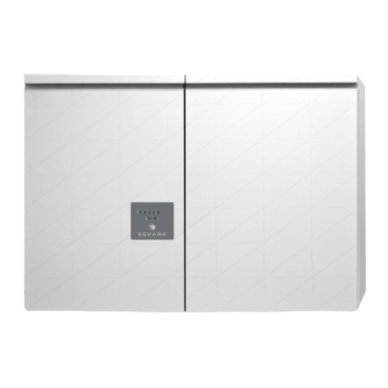
Summary of Contents for Eguana Evolve ESS AU 13
- Page 1 Model Evolve ESS AU – 13 kWh Evolve ESS AU – 26 kWh Evolve ESS AU – 39 kWh Grid Support Utility Interactive Inverter & Integrated Lithium Battery Installation & Start-up Guide For use only with battery model • LG Chem EM048126P3S7...
- Page 2 Revision History Revision Date Status Author Comments 05.Oct.2022 Released Initial release.
- Page 3 (PCS) and base model battery cabinet installation and operation. This product is expandable with the addition of up to two more battery cabinets. The Eguana Evolve™ components described by this manual are intended to be used as part of an Energy Storage system and installed as per the local electrical code.
-
Page 4: Table Of Contents
Contents 1 SAFETY..................................1 1.1 I ........................1 N CASE OF EMERGENCY 1.2 B .................... 1 ATTERY MODULE SAFETY PRECAUTIONS 1.3 G ......................2 ENERAL SAFETY PRECAUTIONS 1.4 E ......................2 NVIRONMENTAL ROTECTION 2 INTRODUCTION ..............................3 2.1 A – T .................. - Page 5 16 TECHNICAL DATA ............................. 20 16.1 PCS ........................20 CABINET DATA 16.2 B ......................... 21 ATTERY CABINET DATA 16.3 W ......................21 IRE AND TORQUE RATINGS 16.4 T .............. 22 HERMAL PERFORMANCE HARGE ISCHARGE URVES APPENDIX A: ELECTRICAL BLOCK DIAGRAM OF INTER-CABINET WIRING ........23 APPENDIX B: ENERGY METER WIRING DIAGRAMS ..................
-
Page 6: Safety
1 Safety Throughout this manual, the following symbols will be used to highlight important information and procedures: Symbol Definition Symbol Definition WARNING! A dangerous voltage or Meter measurement required. other condition exists. Use extreme caution when performing these tasks. CAUTION! This information is critical to the safe installation and or operation of Torque rating critical to operation. -
Page 7: General Safety Precautions
1.3 General safety precautions Important! Installation, service, and operating personnel must read this document in its entirety, and observe all safety and installation procedures as described in this manual. Never operate system in a manner not described by this manual. Only qualified personnel should service this product. -
Page 8: Introduction
AC coupled solar plus storage installation, which is independently supplied, installed, and operated from the Eguana Evolve ESS. It is the responsibility of the installer to ensure that any utility interactive PV system connected to a backup panel for micro-grid operation is compatible for use with a grid-forming battery inverter. -
Page 9: Initial Inspection Of Material List
2.3 Initial Inspection of Material List The system components supplied with your Eguana Evolve™ Energy Storage system are shown below. Each component should be inspected visually for any damage that may have been caused by shipment. If damage is present, please contact your local distributor. -
Page 10: Installation Site Preparation
3 Installation Site Preparation Before installing the Evolve home energy storage components, read all instructions and warnings in this manual. CAUTION! All electrical installation work should be performed in accordance with local building and electrical codes. WARNING! Isolate the PCS from all energy sources prior to electrical installation by means of disconnects, breakers or connectors. -
Page 11: Installation Plan - Power And Communication Circuits
3.3 Installation plan – power and communication circuits The following example outlines the conduit plan for power and communication circuits for the battery system. In this example, the PV inverter is coupled to a backup power sub-panel. The sub-panel may also be an isolated power bus within the main electrical panel. -
Page 12: Sld - Ac Coupled Pv System With Back-Up Power Operation
3.4 SLD - AC Coupled PV System with Back-up Power Operation The single line diagram shown below is a representation of a typical installation configured for utility interactive and back-up power operation, with AC coupled PV connected to a critical load panel. This drawing is a guideline only, and is not a substitute for a code compliant installation. -
Page 13: Pcs And Battery Cabinet Wall-Mounting Instructions
4 PCS and Battery Cabinet Wall-Mounting Instructions Cabinet mounting slot Wall Alignment mount 1. Mount the wall bracket to the wall. Use the available slot pattern to mount to a load-bearing structure rated for the weight of the final system. The slots accommodate a M8 bolt diameter. - Page 14 CAUTION! The PCS cabinet is heavy. Mechanical lift recommended. 10. Lift the PCS cabinet onto the wall mounting bracket. 11. Slide the PCS cabinet to the left such that it aligns with the alignment tab on the mounting bracket. 12. From the rear side of the cabinet, spin the lower levelling bracket (in/out) until the cabinet is vertically plumb (level) to the wall (as shown in step 7).
-
Page 15: Pcs / Battery Inter-Cabinet Wiring
5 PCS / Battery Inter-Cabinet Wiring Plastic barrier The following instructions cover the interconnection wiring of the PCS and master battery cabinet. No cable preparation is required with battery modules pre-installed in the cabinet. Refer to appendix A for a complete inter-cabinet wiring diagram. -
Page 16: Battery Bms To Pcs Communication Connection
5.2 Battery BMS to PCS communication connection BMS CAN port Figure 7: PCS to BMS communication wiring. The communication cable can be routed with DC power cables. Take care that the communication cable is routed through the inter-cabinet coupler so that there is no stress or tension on the terminations. This cable is terminated with RJ-50, 10-pin connectors. -
Page 17: Ac Power Connections
6.1 AC power connections This battery system contains two independent AC power connection ports; one port dedicated for an electrical utility connection, marked “AC Grid”, the other port dedicated for backup operation, marked “AC load”. This product’s primary application is intended for utility interconnection, and must be connected to a utility electrical service supplying single phase 230 Vac / 50 Hz. -
Page 18: Chassis Grounding
6.2 Chassis Grounding In this section, “Chassis Ground” is referred to as “ground” or “grounding” unless otherwise mentioned. The PCS cabinet is shipped with ungrounded DC power terminals within the inverter. When terminated to the batteries, the DC bus is configured for DC negative to ground. AC Grid Earthing System: The AC power grounding is achieved through the PE terminals of the AC grid connectors on the AC Filter Board, as shown in section 6.1. -
Page 19: Rs-485 Communication Connection
This system is supplied with split-core CTs for installation without interruption to the electrical service. The CTs must be mounted on the primary electrical bus, between the main service breaker disconnect and the utility’s energy meter. This is important to ensure all loads and generation are captured for optimum performance of the solar self consumption control algorithms. -
Page 20: Start-Up Sequence
10 Start-up Sequence CAUTION! Powering the Evolve home energy storage system requires a specific start-up procedure. Please follow the steps below. CAUTION! If the battery disconnect has been placed in the OFF position at any time during operation, wait one minute before returning to the ON position. Rapid cycling (less than one minute) of the battery disconnect can cause damage to the pre-charge circuit. -
Page 21: Shutdown Sequence
PCS settings file must be updated accordingly using a separate software application. Contact support at Eguana Technologies Pty to obtain the ECI software. Refer to the Eguana ECI manual for further instructions. PCS settings are not available in the EMS monitoring app. -
Page 22: Pcs Display Panel
12 PCS Display Panel Service Mode PCS Operating Mode Battery SOC Service button 12.1 LED Display Indicators The PCS cabinet is equipped with a display panel that provides indication of the following: • Battery Operating State Figure 15: PCS display panel. •... -
Page 23: Backup Power Operation
12.4 Backup Power Operation This system will provide backup power to dedicated electrical circuits within the home via a permanently wired electrical sub-panel, referred to as the backup panel. Backup power is limited in rating and duration, both of which are dependent on the nature of the loads connected to the system, and the availability of the solar PV supply. -
Page 24: Maintenance
The backup power will restart, allowing the PV system to energize and charge* the battery. The system will continue to operate if the battery charges to its minimal normal operating range. If the battery does not charge within 15 minutes of restart, the system will shut down to preserve the battery. *Australia –... -
Page 25: Technical Data
16 Technical Data 16.1 PCS cabinet data Electrical & performance data, AC Grid voltage 230 / 240 Vac Grid frequency 50 Hz Maximum continuous operating current 21.7 Amps Maximum continuous operating power 5000 VA Power factor, nominal (range) > 0.99 (0.8 lead to 0.8 lag) Efficiency, % peak (average) 96 (94.5) Maximum AC fault current and duration (short circuit) -
Page 26: Battery Cabinet Data
16.2 Battery cabinet data Electrical and performance data Battery module, manufacturer LG-Chem Model EM048126P3S7 Chemistry Lithium NMC Rated energy, per module 6.5 kWh Number of modules per cabinet DC voltage operating range 42.0 to 58.8 Vdc Battery lifetime energy guarantee, per module 19.2 MWh Circuit protection, integrated Breaker, 180 Adc, positive pole... -
Page 27: Thermal Performance: Charge / Discharge Curves
16.4 Thermal performance: Charge / Discharge Curves Evolve ESS AU Charging AC Power Derating 6000 15 to 45°C 5000 10°C 4000 3000 10°C 2000 50°C 1000 SOC (%) Full Range Derated Evolve ESS AU Discharging AC Power Derating 6000 15 to 45°C 5000 5°C 4000... -
Page 28: Appendix A: Electrical Block Diagram Of Inter-Cabinet Wiring
Appendix A: Electrical Block Diagram of Inter-Cabinet Wiring The following reference diagram outlines the DC and communication interconnections between PCS, master battery, and expansion battery cabinets. Reference Title Notes 801003 338 PCS-BMS cable Connects master battery to PCS [BMS CAN] port. 801003 533 BMS cable –... -
Page 29: Appendix B: Energy Meter Wiring Diagrams
Appendix B: Energy Meter Wiring Diagrams Refer to the energy meter supplied with the system. B.1 Accu-Energy Acurev 1310 B.1.1 RS-485 Communication to the EMS To PCS [EMS MBUS] Port Figure 18: EMS to Acurev 1310 energy meter communication wiring diagram. B.1.2(A) Main electrical panel meter CT and power wiring. -
Page 30: Eastron Sdm630Mct-40Ma
B.2 Eastron SDM630MCT-40mA EMS panel electrical block diagram CT wiring RS-485 communication wiring Voltage sense wiring... - Page 31 INSTALLATION NOTES...
- Page 32 Eguana Technologies Inc. Doc. 68118 Rev1 2022...
Need help?
Do you have a question about the Evolve ESS AU 13 and is the answer not in the manual?
Questions and answers