Table of Contents
Advertisement
Quick Links
Advertisement
Table of Contents

Subscribe to Our Youtube Channel
Related Manuals for Calian SatService sat-nms ACU-19V2


Summary of Contents for Calian SatService sat-nms ACU-19V2
- Page 1 Antenna Controller sat-nms ACU-19V2 User Manual Version 5.0.002 © Copyright SatService Gesellschaft für Kommunikationssysteme mbH Hardstrasse 9 D-78256 Steisslingen satnms-support@satservicegmbh.de www.satnms.com www.satservicegmbh.de Tel +49 7738 99791-10...
-
Page 2: Table Of Contents
Table Of Contents Table Of Contents ..........................sat-nms ACU-19V2 User Manual ....................... 1 Introduction ............................2 Safety Instructions ........................... 3 The sat-nms ACU19V2 ........................3.1 Frontpanel Display ........................3.2 Frontpanel Keyboard ......................... 3.3 Drive cabinet interfaces ......................3.4 Analog beacon level input ......................3.5 Angle encoder interfaces ...................... - Page 3 7.3 The RS232 remote control interface ..................7.4 Parameter list .......................... 7.5 One line read via TCP/IP ......................8 Theory of Operation ........................8.1 Angle Measurement ......................... 8.2 Pointing / Motor Control ......................8.3 Steptrack ..........................8.3.1 The sat-nms Steptrack Algorithm ..................8.3.2 ACU and Beacon Receiver ....................
-
Page 4: Sat-Nms Acu-19V2 User Manual
sat-nms ACU-19V2 User Manual Version 5.0.002 -- 2021-07-29 -- © 2003-2021 SatService GmbH Abstract The sat-nms ACU19V2 is an advanced automatic tracking antenna controller. It can be used as a cost efficient antenna tracking system to replace the Vertex / General Dynamics Satcom Technologies Model 7200 Antenna Control Unit keeping the outdoor 7150 Antenna Drive Unit as it is. -
Page 5: Introduction
5.1 The Web-based User Interface 5.2 Antenna Pointing 5.3 Target Memory 5.4 Tracking Parameters 5.5 Test Page 5.6 Setup 5.7 Handheld Terminal 6 Frontpanel operation 6.1 Display mode 6.2 The main menu 6.3 Select targets 6.4 Set tracking mode 6.5 Step move 6.6 Jog mode 6.7 Standby 6.8 Set az, el, pl by editing Numeric Parameters... - Page 6 sat-nms ACU-ODU: complete antenna controller system for AC- or DC-Motors integrated in an outdoor cabinet that could be mounted directly to the antenna. By mounting a sat-nms LBRX beacon receiver into this cabinet, you have a complete antenna tracking system in a compact cabinet directly at your antenna.
-
Page 7: Safety Instructions
the ACU's connectors. It gives you informations about the starting up procedure. Finally you learn in this chapter how to set the ACU's IP address, which is a essential precondition to operate the ACU by means of a web browser. Operation : The sat-nms ACU is operated using a standard web browser like the Internet- Explorer on MS Windows based computers. -
Page 8: The Sat-Nms Acu19V2
To prevent electrical shock, do not remove covers. For the correct and safe use of the instrument, it is essential that both operating and servicing personnel follow generally accepted safety procedures in addition to the safety precautions specified in this manual. Whenever it is likely that safety protection is impaired, the unit must be made in-operative and secured against unintended operation. -
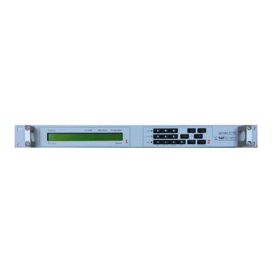
Page 9: Frontpanel Display
sat-nms ACU19V2 Front panel view sat-nms ACU19V2 rear view component component frontpanel display alarm interfaces frontpanel Keyboard remote interfaces drive cabinet interfaces mains input analog beacon level input serial interface angle display angle encoder interfaces 3.1 Frontpanel Display The Display together with the keyboard is your interface for local operation without using e.g. an external computer. -
Page 10: Alarm Interfaces
The sat-nms ACU19V provides the possibility to connect two different types of angle encoders: optical SSI encoders (S) and Resolvers (R). Please refer to chapter Interfaces to the antenna/ Pin descriptions for more detailed informations. You have to decide at point of order which variant you want to have. -
Page 11: Connector Layout
chapters show the standard pin configuration. If you have a non-standard version, please refer to the documentation enhancement that shows the pin descriptions of it. 4.2.1 Connector Layout Below the connector layout of the ACU19V2 is shown. The connector type is described together with the corresponding pin description in the following chapter. - Page 12 MAINT Maintenance (+) MAINT Maintenance (-) J21 Analog beacon level input Connector Type: D-Sub9 female The ACU19V2 preferably is used together with the sat-nms LBRX beacon receiver. With the sat-nms LBRX the ACU talks though UDP or TCP over IP, no additional cabling is required in this case.
- Page 13 When connecting a resolver to the ACU, please consider the following: Use a shielded, twisted pair cable. Connect the cable shield either to the case of the DSub9 connector or to the ground at the resolver housing. Never connect the shield at both ends, this will introduce a ground loop and cause a significant degradation of the resolver's accuracy.
- Page 14 signal description type SHLD Shield drive signal to resolver COS- resolver COS SIN- resolver SIN resolver COS SHLD Shield SHLD Shield REF- drive signal to resolver resolver SIN TB1 Alarm Connector Type: D-Sub9 female TB1 provides a dry contact Alarm Interface for ACU-Alarms and Tracking Alarms signal description...
-
Page 15: Start-Up
Connector Type: D-Sub9 male This interface is not implemented yet and is reserved for further expansions J11 LAN Connector Connector Type: RJ45 male J11 is the Ethernet 10Base-T / RJ45 connector. Use a standard network cable to connect the sat-nms ACU-RMU to an Ethernet hub. If you want to connect your computer and the ACU directly without using a hub, you need a crossover cable for this with swapped RX/TX lines. -
Page 16: Setting The Ip Address
2. Set the ACU's 4.3.1 IP address 4.1 Mechanically mount the ACU19V2. 4.2 Connect the ACU to the antenna (position encoders, motor driver interface). Finally connect the mains power supply and the Ethernet network. 5. Start up the system and set the parameters as described below. 6. -
Page 17: Angle Detectors
empty, the ACU is not connected properly. If there are more entries in the list, the configuration program has found other devices in this network segment which use the same technology. 6. Now open with a right-click the sub-menu 'IP configuration' to open the IP configuration window of the program. -
Page 18: Pointing/ Tracking
4. Check the motor rotating directions, if necessary change it by interchanging the two wire of the motor cable. 5. Drive the antenna in every direction (AZ, EL and POL) until the limit switches stop the motor movement to ensure that the limit switches work well. ATTENTION! While doing this test it is absolutely necessary to be very mindful to check, if nothing collides! 6. -
Page 19: Operation
6. Browse on the left side to the desired location to which you like to save the backup 7. Right-click the app.dat file and choose copy in the drop down list. The file will immediately be copied to the location shown on the left side. If you have saved targets, you might backup them in the same way. - Page 20 and the actual antenna pointing in the main part of the window. The readings automatically refresh once a second. The refresh-rate may be adjusted on the setup-page from software version 2.1.007 or higher. The navigation bar at the left contains a couple buttons which build the ACU's main menu: Pointing : This button switches back to the main page you already see when you connect to the ACU.
-
Page 21: Antenna Pointing
read from the position sensors.STANDBY: The STANDBY button puts the pointing loop of all axes to 'standby' mode: Differences between measured and commanded value do not cause the motors to be driven in this mode. Standby mode can be used for maintenance purposes or to move the antenne by actuating the frequency inverters directly by hardware circuits. - Page 22 by a sat-nms LBRX beacon receiver via TCP/IP of the level derived from the ACU's analog input. Temperature --- The actual temperature inside the ACU enclosure. This value is for information only. ACU Faults --- If there are any faults with the ACU, they are displayed in this field. If there is more than one fault at a time, the ACU concatenated the fault descriptions.
-
Page 23: Target Memory
5.3 Target Memory The page 'Targets' gives access to the ACU's target memory. The ACU is capable to remember the pointing (and tracking parameters, if the ACU has the tracking module installed) of up to 99 satellites. Managing these memories is done with the 'Targets' page. The page displays a table with all pointings actually stored. -
Page 24: Tracking Parameters
the short time storage described above. Targets Page Example: 5.4 Tracking Parameters sat-nms ACUs with the tracking function installed give access to the tracking mode and the fine tune parameter which lets you adapt the tracking to the individual requirements of the antenna and the satellite you are tracking to. - Page 25 mask the level differences caused by the test steps, the antenna will not track the satellite properly.The step size is specified as a percentage of the antenna's half 3dB beamwidth. The ACU calculates the beamwidth from the antenna diameter and the beacon frequency. Expressing the step size in this relative way keeps the value in the same range, regardless of the type of antenna.
-
Page 26: Test Page
simple model calculated from the step track peaks of the recent few hours. A detailed description of this function you find at chapter '8.3.3 Smoothing' Peakjitterthreshold --- If the jitter value of at least one axis exceeds this threshold, the ACU raises an 'model fault'. - Page 27 inactive, OK or 'false'. Read means the signal is active or 'true'. Toggling output levels manually The 'Test' page also lets you toggle the actual state of each output signal simply by clicking to the underlined HI/LO mark of the signal. If you do this, you should consider the following: The ACU sets the motor driver outputs eight times a second for each axis having the motor driver type set to 'DIR-START' or 'DUAL-START'.
-
Page 28: Setup
5.6 Setup The page 'Setup' contains the ACU's installation parameters. The page displays a table with the parameters actually set. Each parameter value is a hyper-link to a separate page which lets you change this parameter. This parameter change page shows the actual parameter setting either in an entry field or in a drop down box. - Page 29 Azimuth / Elevation / Polarization The Azimuth / Elevation / Polarization sections contains the parameters which are specific to the individual axis. They are the same for each axis. Parameter Name --- Description Antenna diameter --- Set this parameter to the dish diameter. Units with the tracking function installed use this value to estimate some tracking parameters.
- Page 30 For the azimuth axis there is another offset which also is taken into account, the 'Antenna course'. This value is provided for mobile applications where a compass reading has to be included into the azimuth value. Calibration scale --- Normally the ACU assumes that the full range of a position sensor corresponds 360°.
- Page 31 Beacon Receiver Parameter Description Name Selects the source of the beacon level the ACU shall use. Available options are SATNMS and VOLTAGE. In SATNMS mode the ACU reads the beacon Beacon RX level from a sat-nms beacon receiver via UDP, in VOLTAGE mode the A/D type converter input of the ACU is read.
- Page 32 UDP port 161. The SNMP agent provides a common subset of the MIB-II system / interface parameters and gives full access to the remote control capabilities of the sat-nms ACU with a number of MIB objects placed in the private.enterprises tree. The actual MIB file defining the ACU's private MIB may be downloaded from the ACU itself by FTP (user 'service', password 'service').
-
Page 33: Handheld Terminal
Setup Page Example 5.7 Handheld Terminal The antenna may be moved by means of the optional handheld controller. The Handheld function is not yet available at ACU-RMU and ACU19 Version. Startup Set parameter 'RS485 address' on the ACUs Setup-page to 'TERM'. This enables communication between the ACU and the sat-nms handheld. -
Page 34: Frontpanel Operation
Cabinet: 15pol DSUB). After connecting the Handheld, push the Redraw button once. The start- up screen, that shows the installed software version is displayed for a few seconds. After that the menu for controlling the antenna is displayed automatically. Operation --- Emergency STOP, stops all Motors immediately, it has to be released by pushing the -button --- Releases the motor-lock that was set by pushing the STOP-button. - Page 35 operation are designed to operate the ACU locally. It is possible to select a new target, move the antenna incremental, set new pointing angles or select another step track mode. Advanced configuration parameters are available over the web interface. Please start reading at chapter 5.1 for more information.
-
Page 36: Display Mode
If one or all motors are moving, they can stop with the following key: 0 --- Stop every motor Postion regulation is off. An Alarm will displayed 1 and 3 --- Select the STANDBY Operation Mode. No Alarm will displayed 1 and --- Stop every motor Postion regulation is on 6.1 Display mode... -
Page 37: Select Targets
MENU SELECT TARGET SET TRACKING MODE STEP MOVE JOG MODE STANDBY SET AZIMUTH SET ELEVATION SET POLARIZATION To navigate in the menu, use . To select a menu press . Pressing once returns to the main menu level, pressing it twice returns to display mode. 6.3 Select targets In the SELECT TARGET menu, it is possible to select a saved target. -
Page 38: Jog Mode
Press a key one time, moves the antenna one step in the corresponding direction. The step size is defined at the Web interface. 6.6 Jog mode The antenna can be moved over the front panel with the JOG MODE menu. The corresponding keys are listed below: 7 --- Move the polarization counterclockwise 9 --- Move the polarization clockwise... -
Page 39: Remote Control
leaves the editing mode without changing anything. 7 Remote Control The sat-nms ACU may be controlled remotely by a monitoring and control application either through the TCP/IP interface or through a serial RS232 interface (RS232 not yet implemented in ACU19 and ACU-RMU). Both communication methods use the same commands and parameters. However, there are different frames around each message depending communication method used. -
Page 40: The Tcp/Ip Remote Control Interface
Assigning a value to a read-only parameter will cause no fault, however the ACU will overwrite this parameter immediately or some seconds later with the actual value. 7.2 The TCP/IP remote control interface Controlling the ACU through the network is done by means of HTTP GET requests. Setting parameter values or querying readings or settings, all is done by requesting HTTP documents from the ACU. -
Page 41: Parameter List
The checksum byte is calculated using an algorithm as implemented by the following formula: This protocol type is known as MOD95- or Miteq protocol . The ACU also packs its reply in a protocol frame as described above. Incomplete frames, checksum errors or address mismatches let the ACU ignore the message. - Page 42 alat -90.000 .. 90.000 °N Antenna latitude Antenna alon -180.000 .. 180.000 °E longitude amax -3600.000 .. 3600.000 ° AZ Upper limit amdt character string AZ Model type amin -3600.000 .. 3600.000 ° AZ Lower limit AZ Maximum ammx SMALL MEDIUM LARGE model type Antenna mount amnt...
- Page 43 Beacon RX IP bcip aaa.bbb.ccc.ddd address Calculate level bclc offset Beacon RX 0V bcof -200.00 .. 0.00 level Beacon RX bcsc -5.0000 .. 5.0000 V/dB voltage scale bcty SATNMS,VOLTAGE Beacon RX type blev #.## Beacon level bofs #.## Level offset Beacon level brip #.##...
- Page 44 EL model ecoe see below coefficients EL Pointing ehys 0.000 .. 2.000 ° hysteresis einv NORMAL INVERTED EL Sense invert ejtr 0 .. EL Peaking jitter emax -3600.000 .. 3600.000 ° EL Upper limit emdt character string EL Model type emin -3600.000 ..
- Page 45 GPS receiver gpty NONE type 3) Input bits ibit 00000000 .. FFFFFFFF (described below) Inclinometer icty NONE type 4) ipt1 SNMP trap IP 1 ipt2 SNMP trap IP 2 ipt3 SNMP trap IP 3 ipt4 SNMP trap IP 4 Invalid ivpr parameter value Peak jitter...
- Page 46 PO Motor driver pmot DUAL-START DIR-START NONE type PO Pre scale pofs ######## offset ppos -90.000 .. 90.000 ° PO Pointing praw 00000000 .. FFFFFFFF PO raw pointing PO Calibration psca 0.000000 .. 100000.000000 scale SSI-13B SSI-13G SSI-17B SSI-17G SSI- 18B SSI-18G SSI-19B SSI-19G SSI-20B PO Position psen...
- Page 47 Tracking model tage Tracking cycle tcyc 1 .. 1638 time tdly 100 .. 9999 msec Recovery delay Target tdsc 0..99 / character string description 7) temp °C Temperature Tracking fault tflt 00 .. FF bits (described below) Tracking thrs memory time character string Date / time 6)
- Page 48 ACU variants with GPS support provide other choices beside NONE for this parameter. 4) ACU variants with inclinometer support provide other choices beside NONE for this parameter. 5) for single step move, use following commands: command description Azimuth large step left Azimuth small step left Azimuth small step right Azimuth large step right...
- Page 49 IN_AZFLT azimuth motor fault IN_EMERG emergency stop IN_ELHLM elevation hi limit IN_ELLLM elevation lo limit IN_ELFLT elevation motor fault IN_COPEN cabinet open AZMOV azimuth moving ELMOV elevation moving PLMOV polarization moving MOVING moving summary bit AZTOT azimuth timeout ELTOT elevation timeout PLTOT polarization timeout TIMEOUT...
- Page 50 OUT_AUX1 not used OUT_AUX2 not used OUT_EL_FWD elevation motor forward OUT_EL_REV elevation motor reverse OUT_EL_SPD1 elevation motor low speed OUT_EL_SPD2 elevation motor hi speed OUT_EL_RESET elevation motor driver reset OUT_EL_RESERVE reserved for extended motor control OUT_AUX3 not used OUT_AUX4 not used OUT_POL_FWD polarization motor forward OUT_POL_REV...
-
Page 51: One Line Read Via Tcp/Ip
APEAKFLT azimuth peaking fault EPEAKFLT elevation peaking fault MODELFLT model match fault JITTRFLT jitter fault not used not used not used not used Tracking coefficients on 'acoe' / 'ecoe': In adaptive tracking mode the 'acoe' / 'ecoe' commands may be used to read the coefficients of the actual model. -
Page 52: Theory Of Operation
8 Theory of Operation This section gives some background information about how the ACU works. Chapter 8.1 Angle Measurement describes how the ACU measures the antenna pointing and how it calculates the angles displayed at the user interface. Chapter 8.2 Pointing / Motor Control describes the way the ACU performs the antenna pointing and how it controls the motors. -
Page 53: Pointing / Motor Control
view, the ACU accepts and displays pointing angles as floating point numbers with 0.001° resolution. Internally the software treats angles as 32 bit integer numbers where the full 32 bit range corresponds to 360°. This is equivalent to a resolution of 0.000000084°. When the software calculates the pointing angles from the sensor readings, it includes some calibration parameters configurable at the Setup... -
Page 54: Steptrack
motor on for both directions or for the forward direction only. REV --- Depending on the motor driver type configured, this signal reverses the motor direction or it activates the motor in reverse direction. SPD1 --- This signal is active while the ACU wants to run the motor slowly. SPD2 --- This signal is active while the ACU wants to run the motor fast. -
Page 55: The Sat-Nms Steptrack Algorithm
receiver to be connected to the ACU, the file/program tracking works without any beacon measurement. 8.3.1 The sat-nms Steptrack Algorithm The principle of satellite step tracking is quite simple: For each axis, move the antenna a small amount away from the satellite, move it a small amount to the other site and finally point the antenna to that position where the signal is the strongest. -
Page 56: Acu And Beacon Receiver
The diagram above shows the sequence of steps the tracking algorithm performs in one cycle on one axis. It starts with a depointing step in one direction (A). If this step lets the signal level decrease, the antenna makes a double step in the opposite direction. It the first step leads to a better receive level, the tracking algorithm adds one or two steps in the same direction. -
Page 57: Smoothing
If a sat-nms LBRX beacon receiver is used with the ACU, it additionally gets connected to the ACU through an Ethernet cable. Usually an Ethernet hub is used to connect the ACU, the LBRX and the controlling computer. With a sat-nms LBRX beacon receiver some additional features are available for the tracking: The beacon receiver sends the actual level as UDP packets over the LAN. -
Page 58: Steptrack Parameters
recently evaluated peak position. The usage of the smoothing function is recommended when tracking satellites where the antenna pointing oscillates less than 25% of the antenna's 3dB beamwidth. For tracking inclined orbit satellites, the usage of smoothing may be problematic as such satellites may require an significant position oscillation at 12 hours cycle time (sin 2wt). -
Page 59: Adaptive Tracking
receiver, the ACU automatically reads the frequency from the receiver. Trackingcycletime --- The cycle time specifies how often the ACU shall perform a step track cycle. The value is to be entered in seconds. In fact, the parameter does not specify a cycle time but the sleep time between two tracking cycles. -
Page 60: The Sat-Nms Adaptive Tracking Algorithm
8.4 Adaptive Tracking Adaptive tracking is an extension to the standard step track method. The ACU records the tracked positions over several days. It computes a mathematical model from the recorded data which is used to predict the antenna position in case of a beacon receive failure. The following paragraphs describe how the sat-nms adaptive tracking algorithm works. - Page 61 plain sine function may be tracked with the MEDIUM model. The amplitude of the double frequency sine simply is near zero in such a case. Finally the LARGE model adds a linear movement to the components of the MEDIUM model. This is required to track significantly inclined satellites over a period of several days.
-
Page 62: The Tracking Memory
Quality information As mentioned above, the amplitude of the satellite's movement is used as a measure of the step track quality. This is because the step track measurement uncertainty is an constant angle which primarily depends on the antenna size. Beside the amplitude, the ACU evaluates for each axis a figure called jitter. -
Page 63: Adaptive Tracking Parameters
M emory reset The contents of the tracking memory must be erased when the ACU starts to track a new satellite. This is done in the following situations: A stored position (target) is recalled. The ACU is switched off. 'CLEAR MEMORY' is chosen at the tracking parameters page. -
Page 64: Program Tracking
to 'STEP', the ACU leaves the antenna where it is if the beacon level drops below the limit.Adjusting the threshold level that adaptive tracking is switched as expected must be done carefully and may require some iterations, specially if the beacon is received with a low C/N. -
Page 65: File Format
next 'tracking interval'. Be aware, that the clock in the ACU must be set precisely to make the feature work as expected. 8.5.2 File Format The "program.txt" file is a plain text file containing a three or four column table. Empty lines are ignored, comments starting with a '#' as well. -
Page 66: Specifications
If a fault stay active in one axis and don't disappear during a RESET, the tracking stops the operation. For example if the polarisation have a fault, azimuth and elevation stop the tracking operation. 9 Specifications Technical Specification Position Encoding with three different interface possibilities --- Resolver, digital SSI and potentiometer Quantization Error --- Resolver 16bit: 0.0055°, SSI 13bit 0.044°, 16bit 0.0055°, 17bit 0.0028°, 19bit 0.0007°...
Need help?
Do you have a question about the SatService sat-nms ACU-19V2 and is the answer not in the manual?
Questions and answers