Table of Contents
Advertisement
Quick Links
Advertisement
Table of Contents

Related Manuals for Calian SatService sat-nms ACU2-19V2


Summary of Contents for Calian SatService sat-nms ACU2-19V2
- Page 1 Antenna Controller sat-nms ACU2-19V2 User Manual Version 2.0.014 © Copyright SatService Gesellschaft für Kommunikationssysteme mbH Hardstrasse 9 D-78256 Steisslingen satnms-support@satservicegmbh.de www.satnms.com www.satservicegmbh.de Tel +49 7738 99791-10...
-
Page 2: Table Of Contents
Table Of Contents Table Of Contents ..........................sat-nms ACU2-19V2 User Manual ..................... 1 Introduction ............................2 Safety Instructions ........................... 3 The sat-nms ACU19V2 ........................3.1 Frontpanel Display ........................3.2 Frontpanel Keyboard ......................... 3.3 Drive cabinet interfaces ......................3.4 Analog beacon level input ......................3.5 Angle encoder interfaces ...................... - Page 3 6.2 The main menu ........................6.3 Select targets .......................... 6.4 Set tracking mode ........................6.5 Step move ..........................6.6 Jog mode ..........................6.7 Standby ........................... 6.8 Set az, el, pl by editing Numeric Parameters ................. 7 Remote Control ..........................7.1 General command syntax ....................... 7.2 The TCP/IP remote control interface ..................
-
Page 4: Sat-Nms Acu2-19V2 User Manual
sat-nms ACU2-19V2 User Manual Version 2.0.014 -- 2021-07-29 -- (C) 2020-2021 SatService GmbH Abstract The sat-nms ACU19V2 is an advanced automatic tracking antenna controller. It can be used as a cost efficient antenna tracking system to replace the Vertex / General Dynamics Satcom Technologies Model 7200 Antenna Control Unit keeping the outdoor 7150 Antenna Drive Unit as it is. - Page 5 5.1 The Web-based User Interface 5.2 Antenna Pointing 5.3 Target Memory 5.3.1 How to make a new target 5.4 Tracking Parameters 5.5 Test Page 5.6 Setup 5.7 Handheld/ Frontpanel Operation 5.7.1 LCPH (Local Maintenance Controller) 5.7.2 LCPHD-PT (Local Maintenance Controller with Display) 5.7.3 RCPH (ACU Handheld Controller) 5.7.4 RCPH19 (ACU Handheld Controller 19") 5.7.5 Handheld Terminal...
-
Page 6: Introduction
8.7.1 Intelsat eleven Parameter Prediction (I11) 8.7.2 Two Line Elements Prediction (TLE) 8.8 Polarization Prediction 8.9 Faults and Tracking 9 Specifications 1 Introduction The sat-nms Antenna Control Unit is an antenna controller / positioner with optional satellite tracking support. It may be operated as a standalone unit or in conjunction of the sat-nms ACU- IDU, a PC based indoor unit which offers extended tracking capabilities and a full featured visualization interface. - Page 7 does the decoding of the resolver sin/cos signals. SSI Interface: SSI is a high speed serial interface used by modern digital position encoders. DC Voltage Interface: The third position encoder interface module contains an A/D converter which is suited to measure the DC voltages produced by simple inductive angle encoders.
-
Page 8: Safety Instructions
Germany phone +49 7738 99791-10 www.satnms.com 2 Safety Instructions Safety The mains shall only be connected provided with a protective earth wire. Any interruption of the protective wire, inside or outside the sat-nms ACU, is likely to make the unit dangerous. Intentional interruption is prohibited. -
Page 9: Frontpanel Display
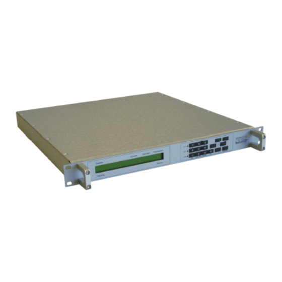
Technologies Model 7200 Antenna Control Unit keeping the outdoor 7150 Antenna Drive Unit as it is. The replacement is simple plug & play by reusing the existing cables. The system is based on the sat-nms ACU-ODM Module and provides Model 7200 ACU fully compatible rear panel connectors in the 19??? 1RU chassis. -
Page 10: Analog Beacon Level Input
The sat-nms ACU19V contains a Vertex / General Dynamics Satcom Technologies Model 7200 compatible drive Interface. This interface commands the external driver unit to move the antenna in 3-axis. Please refer to chapter Interfaces to the antenna/Pin descriptions for more detailed informations. -
Page 11: Mechanical Installation
4.1 Mechanical installation The sat-nms ACU19V2 is completely integrated into a 1RU 19inch case with standard mounting holes. The case of the sat-nms ACU19V2 is not strong enough to carry the complete unit only on the front mounting holes! Because of that, take care that the sat-nms ACU19V2 is placed onto a bar guide that carries the complete weight of the sat-nms ACU19V2. - Page 12 Sum Lim Sum Limit (+) Az FLT Az Fault (+) El FLT El Fault (+) E-Stop E-Stop (-) Com FLT Az El Fault Common(-) Sum Lim Sum Limit (-) E-Stop E-Stop (+) Az HSP Azimuth high Sp Cmd El HSP Elevation high Sp Cmd DRV EN Az/El Drive Enable Cmd...
- Page 13 connected either to pin xxx at the ACU or to the ground at the encoder housing, never at both ends. The power supply outputs are internally fused. Be aware not to cause a short circuit. If this happens, the unit has to be opened and the fuse has to be replaced. Do not open the unit by yourself, you will loose warranty in that case.
- Page 14 SHLD Shield REF- drive signal to resolver resolver SIN J5 Resolver interface (Option 4th Axis) Connector Type: D-Sub9 female. The ACU resolver interface is designed for resolvers with an impedance of 100 Ohms or more and transfer factor 0.5. The interface applies 4Veff / 2000Hz to the resolver drive coil. It expects 2Veff at the sine / cosine inputs at the maximum positions.
- Page 15 When connecting a resolver to the ACU, please consider the following: Use a shielded, twisted pair cable. Connect the cable shield either to the case or pin 1,6,7 of the DSub9 connector or to the ground at the resolver housing. Never connect the shield at both ends, this will introduce a ground loop and cause a significant degradation of the resolver's accuracy.
- Page 16 The ACU Linear (LP)/ Circular(CP) Switch interface is designed to control the mode switching of an antenna by providing a switch command via relay output and indication inputs via optocouplers. The indication polarity (NC or NO) can be defined in the ACU setup. When connecting a CP/LP Switch to the ACU, please consider the following: The relay outputs are designed for 30VDC/ 2A maximum.
- Page 17 AUX 3 A Aux 3 Input Anode AUX 4 A Aux 4 Input Anode AUX 5 A Aux 5 Input Anode (only 4th Axis Option) AUX 6 A Aux 6 Input Anode (only 4th Axis Option) AUX 7 A Aux 7 Input Anode (only 4th Axis Option) AUX 8 A Aux 8 Input Anode (only 4th Axis Option) Az-Limit CW...
-
Page 18: Start-Up
ACU RS232 TX ACU RS232 RX n.c. not connected Signal Ground 6..9 n.c. not connected J9 LAN Connector Connector Type: RJ45 mal J9 is the Ethernet 10Base-T / RJ45 connector. Use a standard network cable to connect the sat- nms ACU-RMU to an Ethernet hub. If you want to connect your computer and the ACU directly without using a hub, you need a crossover cable for this with swapped RX/TX lines. -
Page 19: Setting The Ip Address
To setup the ACU's IP parameters, the PC used for configuring and the ACU must either be connected to the same Ethernet hub or must be connected directly with a crossover cable. The initialization program does not work through routers or intelligent network switches. Hence, the typical sequence of tasks when putting an sat-nms ACU19V2 into operation is as follows: 1. -
Page 20: Angle Detectors
5. The serial number of the core module shown in the first column of the list. If the list stays empty, the ACU is not connected properly. If there are more entries in the list, the configuration program has found other devices in this network segment which use the same technology. -
Page 21: Driver Interface
you need to type in here the exact values). 3. Check the rotational direction of the encoders. If possible, do this by turning the encoder axis directly, otherwise you have to move the antenna by hand. Maybe you have to invert the rotational direction on the setup page. -
Page 22: Operation
displayed IP, you might adjust it in the drop-down list here. 4. Login with username service and password service 5. Now you see on the right side the file system of the ACU like shown on the following picture. On the left side you see the computers file system. 6. -
Page 23: The Web-Based User Interface
5 Operation The sat-nms ACU outdoor module is designed to be controlled over a network link using a standard web browser. This means in practice, that the user interface to the ACU appears in your browser window after you type in the ACU's IP address in the address field of the browser program. -
Page 24: Antenna Pointing
Target : By clicking to this button you switch to the 'Target' page where you can store and recall the antenna pointing for up to 200 satellites. Orbital Data : By clicking to this button you switch to two pages where you can store and recall up to 99 sets of TLE ephemeris data and 99 sets if I11 satellite data. - Page 25 The table below describes the information shown by this page: Azimuth Elevation Polarization --- The bold printed figures show the actual antenna pointing angles as read from the position sensors. If the polarization axis is not controlled by the ACU, '-.---??' is displayed in the polarization field. ACU versions equipped with a fourth axis show four columns here, the fourth column labeled "Polarization 2".
-
Page 26: Target Memory
Beacon level --- This field shows the beacon level as read from the beacon receiver. Depending on the source defined at the Setup page, this either is the beacon level reported by a sat-nms LBRX beacon receiver via TCP/IP of the level derived from the ACU's analog input. - Page 27 Below the target table the ACU shows the actually selected target, the initial pointing mode to be used with the next Go command anf the save mode. Actually selected: This displays the name and number of the actually tracked satellite as well as the currently active tracking mode.
-
Page 28: How To Make A New Target
5.8 Target Editor describes this function more detailled. Delete --- Analogous to the 'Save' icon, the table shows an eraser icon in the 'Delete' column. The icons only are shown for the memory locations which are in use. Clicking to the eraser icon clears the selected memory location after a confirmation inquiry. -
Page 29: Tracking Parameters
Set the Level threshold in the tracking menu to a large value e.g. -100dB. Set the new Pointing Angles (e.g. Center of the Box) of the new satellite. If TLE or I11-Parameter for the satellite available (Menu Orbit Data), choose the corrosponding Prediction Parameters. - Page 30 OFF --- No tracking is performed. STEP --- Step track mode. In regular intervals, the antenna performs small search steps to optimize the pointing. Chapter '8.3.0 Step Track' gives more information about this mode. STEP-TLE --- The antenna tries to optimize its pointing like in STEP mode. If the level of the received signal is too low for this optimization, the antenna moves along the path calculated from a TLE parameter set instead.
- Page 31 applied. The Pol angle is set to its stored position in this mode. After the commanded position has been reached, the tracking selected by the 'tracking mode' is started. M ODEL --- The antenna's Az/El angles are calculated from the adaptive tracking model stored with the recalled target memory.
- Page 32 to start with 20% and try to reduce down to 15% if the signal degradation during tracking becomes too high.The tracking step size is a common parameter for both axes. If both axes behave differently, you can tweak the antenna diameter settings in the setup. Specifying a larger diameter makes the ACU using a smaller step size for this axis.If the tracking step seems to be completely out of range, you should check if the beacon frequency is set properly.
- Page 33 elevation may move several degrees while the azimuth shows almost no motion. M easurement delay --- During a steptrack cycle, the ACU positions the antenna to a certain offset and then measures the level. Between the moment when the antenna reached commanded position and the beacon level measurement the ACU waits some time to let the beacon level settle.
- Page 34 threshold monitoring completely off. Prediction Parameters I11 Ephemerides --- The ACU provides 99 named memory places (numbered 1..99) to store Intelsat 11 parameter sets. With this parameter you address the number of the I11 parameter set to be used with the 'I11' or 'STEP-I11' tracking modes and for the 'I11' intitial pointing mode as well.
- Page 35 falls below this value, the receiver states a receive level fault. To disable the level alarm, set the threshold to a very low value, e.g. -120 dBm.Please note, that the threshold value refers to the signal level, even if the receiver operates in a C/N measurement mode. C/N Noise measurement --- With this parameter you select if the receiver shall perform a plain input level measurement or a C/N measurement.
-
Page 36: Test Page
display gets compensated for the selected modulation type. CLEAR TRACKING M EM ORY Clicking to this mark clears the tracking memory. You should do this when you start to track a new satellite. Clearing the tracking memory about half an hour after tracking started significantly improves the quality of the first adaptive tracking model which will be evaluated after 6 hours of tracking. -
Page 37: Setup
Logical I/O Levels The logical level of an input or output is described by it's color: Green means this signal is inactive, OK or 'false'. Read means the signal is active or 'true'. Toggling output levels manually The 'Test' page also lets you toggle the actual state of each output signal simply by clicking to the underlined HI/LO mark of the signal. - Page 38 The table below lists the settings provided by this page. General This section of the setup page contains some general setup parameters. Note --- The text you enter here appears as the title of the main page of the ACU WebGUI. You may want to set this to a descriptive name of the Antenna controlled by this ACU.
- Page 39 window. Watchdog pulse on AUX8 --- The AUX 8 output may be configured to act as a heartbeat output. If enabled, the output switches every 1000 ms between on/off. If using this signal for an external watchdog circuit, be aware that in adaptive tracking mode delays of some seconds are possible while the acu calculates the orbital model.
- Page 40 type position sensors. The selected sensor type must match the type of interface board installed in your ACU. It is not possible to switch from SSI to RESOLVER or vice versa without changing the interface module.When selecting a SSI type position encoder, also the number of bits and the encoding scheme must be selected.
- Page 41 Polarization: The feed turns clockwise (when looking through the antenna to the satellite) for increasing values. When operated on the southern hemisphere, the polarization sense must be set the other way round. M otor driver type --- The ACU knows two different configuration modes to control a motor driver.
- Page 42 timestamps. If no NMEA messages are received, the ACU states a fault. Antenna course --- The Antenna course is an additional offset which is included into the azimuth calibration. It is used for mobile antennas to set the orientation of the antenna without recalibrating it.
-
Page 43: Handheld/ Frontpanel Operation
parameters of the ACU, including the setup and the tweaks on the test page. 5.7 Handheld/ Frontpanel Operation The antenna may be moved by means of the optional handheld or frontpanel controller. There are five different version available which will be supported by the sat-nms ACU: LCPH , a very basic handheld which allows the movement of all three axis. -
Page 44: Rcph (Acu Handheld Controller)
The LCPHD-PT is very simular to LCPH, but with angular Display and PT-Connector for direct connection to the outdoor cabinet. Have a look to the previous chapter for the description. Remark: Requires LCPH-PT-UP if sat-nms ACU-ODU-AC was delivered before 5/2018. 5.7.3 RCPH (ACU Handheld Controller) The RCPH is a ruggedized control panel which is useable to control the basic settings of the ACU without the need of a Ethernet connection. -
Page 45: Handheld Terminal
The RCPH19 is very simular to the RCPH, but mounted in a 1RU 19 Inch rack drawer. Have a look to the previous chapter for the description. Remark: Requires RCPH-UP for sat-nms ACU-ODU-xx to realize the interconnection. 5.7.5 Handheld Terminal Startup Set parameter 'RS485 address' on the ACUs Setup-page to 'TERM'. -
Page 46: Target Editor
--- Turns the polarisation clockwise --- Moves the antenna up (EL) --- Moves the antenna to the left (AZ) --- Stops the antenna movement (only in continuous mode) --- Moves the antenna to the right (AZ) --- Moves the antenna down (EL) Remark: This unit is not longer available, but still software supported from the sat-nms ACU- ODM. - Page 47 M EM ORY --- The antenna tries to optimize its pointing like in STEP mode. If the level of the received signal is too low for this optimization, the antenna moves to the position it had exactly one siderian day before. ADAPTIVE --- The adaptive tracking mode works the same way as step track, but it additionally is capable to predict the satellite's position when the beacon reception fails.
- Page 48 position shall be moved in the PROGRAM, I11 and TLE tracking modes. Polarization prediction --- Actually not implemented. Target orbit position --- The nominal orbit position of the satellite (??E). This value is used for the initial pointing of the antenna if the 'initial pointing mode' is set to 'ORBIT'. Inclination --- Actually not implemented.
- Page 49 mode is selected. If the tracking mode is set to 'STEP', the ACU leaves the antenna where it is if the beacon level drops below the limit.Adjusting the threshold level that adaptive tracking is switched as expected must be done carefully and may require some iterations, specially if the beacon is received with a low C/N.
- Page 50 Peak jitter threshold --- If the jitter value of at least one axis exceeds this threshold, the ACU raises an 'model fault'. If this happens three consecutive times, the ACU resets the models of both axes. Adaptive tracking will be possible not until 6 hours after this happens.During adaptive tracking, the ACU evaluates for each axis a figure called jitter.
-
Page 51: Orbital Data Editor
Please note, that the ACU-ODM uses one single temporary memory for the target editor. The implies that the target editor may not be used from more than one browser window at a time or the edited values will be messed up. This also applies to a remote controlled edit session, either a target memory may be edited in the WebGUI or via an external software, not from both sources at the same time. -
Page 52: Tle Dataset Editor
At the end of each of the data set editor chapters you find a step by step instruction how to upload a complete set of 99 TLE or I11 datasets with FTP and how to make the ACU use the new data. - Page 53 TLE Dataset Editor Page Example: You may use copy&paste to get the TLE data from the external source into this form field, this is a convenient way to edit or update single TLE datasets at the ACU. Beside this, the ACU permits to upload a text file with all 99 datasets with FTP.
-
Page 54: I11 Dataset Editor
and log in with user name 'service', password 'service'. Then upload the TLE.TXT file to the default directory on the ACU. You may be asked to confirm if the existing TLE.TXT file shall be overwritten. Step 3: reload the TLE.TXT file in the ACU software For this last step open the Orbital Data Editor page from the navigation bar and ensure that the... - Page 55 For Intelsat ephemerides there is no compact standard format defined as is for TLE ephemerides, hence entering each particular parameter into the form shown above is the way to edit or update single I11 datasets at the ACU. Beside this, the ACU permits to upload a text file with all 99 datasets with FTP. This way you may update / replace all I11 data at once.
-
Page 56: Frontpanel Operation
Line 1 contains the satellite name Line 2 contains the epoch time and the 11 parameters of the satellite model. They have to be formatted as a semicolon separated line containing the coefficients in the following order: EPOCH;LM 0;LM 1;LM 2;LONC;LONC1;LONS;LONS1;LATC;LATC1;LATS;LATS1 The epoch has to be (exactly) defined in the format 'YYYY MM DD HH MM SS'. -
Page 57: Display Mode
The 'Move' LED is on while a motor is on. The 'Limit' LED is on while an end switch of the antenna is activated. If so, the 'Alarm' LED is also on. The 'Alarm' LED is on while the ACU19 is in alarm state. Keys The front panel keyboard provides beside the numeric keys four arrow keys and two keys named ENTER and CLEAR. -
Page 58: The Main Menu
tracking mode, the default display looks like this: or alternative The upper display line shows the actual target name and the three axes angles. The lower line shows the selected tracking mode or alternative the remaining time between the tracking steps (selected with arrow up/down), depending on tracking mode, the size of the tracking memory and the model data or nothing, and the beacon level. -
Page 59: Select Targets
SET TRACKING MODE STEP MOVE JOG MODE STANDBY SET AZIMUTH SET ELEVATION SET POLARIZATION SET POLARIZATION 2 (only with the 4-axis model) To navigate in the menu, use . To select a menu press . Pressing once returns to the main menu level, pressing it twice returns to display mode. 6.3 Select targets In the SELECT TARGET menu, it is possible to select a saved target. -
Page 60: Jog Mode
6 --- Move the polarization 2 clockwise Press a key one time, moves the antenna one step in the corresponding direction. The step size is defined at the Web interface. 6.6 Jog mode The antenna can be moved over the front panel with the JOG MODE menu. The corresponding keys are listed below: 7 --- Move the polarization counterclockwise 9 --- Move the polarization clockwise... -
Page 61: Remote Control
The lower display line shows the actual value. You enter the new value, using the number keys. The arrow up key adds a (-) in front of the numeric value and the arrow down adds a (.). The key clears the entered value. To accept the edited value, press . -
Page 62: The Tcp/Ip Remote Control Interface
device will reply only a fixed number of places. The ACU recognizes a decimal point ('.'), numbers must not contain any commas. There must not be any whitespace in front or after the '=' in a message. If the command/query is not of the form name=value or name=? , the ACU replies the message ?SYNTAX . -
Page 63: Parameter List
last character of the message body n .tc} end character, always '} ' checksum The checksum byte is calculated using an algorithm as implemented by the following formula: This protocol type is known as MOD95- or Miteq protocol . The ACU also packs its reply in a protocol frame as described above. - Page 64 addr A B C D E F G NONE TERM RS232 address ahys 0.000 .. 2.000 AZ Pointing hysteresis ainv NORMAL INVERTED AZ Sense invert ajog R r x f F AZ jog commandt ajtr AZ Peaking jitter alat -90.000 .. 90.000 Antenna latitude alon -180.000 ..
- Page 65 bcfr 1000.000 .. 40000.000 Beacon RX frequency bcip aaa.bbb.ccc.ddd Beacon RX IP address bclc Calculate level offset bcof -200.00 .. 0.00 Beacon RX 0V level bcsc -5.0000 .. 5.0000 V/dB Beacon RX voltage scale bcty sat-nms VOLTAGE Beacon RX type 1200 2400 4800 9600 bdrt RS232 baudrate...
- Page 66 eamp EL Amplitude ecal -3600.000 .. 3600.000 EL Calibration offset Calculate offset from El. eclc value ecoe see below EL model coefficients ehys 0.000 .. 2.000 EL Pointing hysteresis einv NORMAL INVERTED EL Sense invert ejog R r x f F EL jog command ejtr 0 ..
- Page 67 ftri interval ftrk OFF ON BCRX Frequency tracking BCRX Frequency tracking ftrw width goto 0 .. 199 Goto target gper GPS error status gpsa GPS satellites gpty NONE NMEA GPS receiver type Use hub-fault as summary hfsl OFF ON limit i11c 1 ..
- Page 68 mdly 0 .. 9999 msec Measurement delay BCRX C/N measurement mmod OFF C/N C/N0 mode BCRX Measurement msbw 6 12 30 100 bandwidth msct 0 .. 999 msec Measured software cycle 1 stops all motors (STOP at the Web UI), 0 releases the stop (RESET at the mstp 0 ..
- Page 69 ppos -90.000 .. 90.000 PO Pointing pprd OFF ON ADAPTIVE Polarization prediction 10) ppst Pol prediction status 10) praw 00000000 .. FFFFFFFF PO raw pointing Single prediction prds calculation pred Prediction file creation psca 0.000000 .. 100000.000000 PO Calibration scale SSI-13B SSI-13G SSI-17B SSI-17G SSI-18B SSI-18G SSI-19B SSI-19G SSI-20B...
- Page 70 SSI-19B SSI-19G SSI-20B PO2 Position sensor type qsen SSI-20G SSI-24B SSI-24G RESOLVER VOLTAGE NONE PO2 Low speed threshold qsth 0.0 .. 10.0 qstp 0.000 .. 90.000 PO2 Step delta 11) qtar -90.000 .. 90.000 PO2 target value 11) qtot 0 .. 32000 msec PO2 Motor timeout 11) rcom...
- Page 71 Sets date / time, command stim character string only 6) sver character string Software version tage Tracking model age taof -180.000 .. 180.000 Target azimuth offset tcom SNMP trap community tcyc 1 .. 1638 Tracking cycle time Target directory (HTTP tdir only) tdly...
- Page 72 STEP-TLE STEP-I11 tmod Tracking mode 9) MEMORY TLE I11 PROGRAM tmxa 0 .. 999 max. TLE/I11 age tnam character string Target name torb -360.000 .. 360.000 Target orbit position trcd 0 .. 1 Target position reached trst 1 .. 1 Reset tracking memory trty NEVER ONCE FOREVER...
- Page 73 Copy of 'cnmf' in the target ecnmf same as 'cnmf' editor Copy of 'cnmi' in the target ecnmi same as 'cnmi' editor Copy of 'ctar' in the target ectar same as 'ctar' editor Copy of 'daco' in the target edaco same as 'daco' editor Copy of 'dacs' in the target...
- Page 74 Copy of 'ptar' in the target eptar same as 'ptar' editor Copy of 'qtar' in the target eqtar same as 'qtar' editor Copy of 'rxpl' in the target erxpl same as 'rxpl' editor Copy of 'scmp' in the escmp same as 'scmp' target editor Copy of 'sdly' in the target esdly...
- Page 75 Copy of 'trty' in the target etrty same as 'trty' editor Copy of 'tstp' in the target etstp same as 'tstp' editor Copy of 'ttle' in the target ettle same as 'ttle' editor Remarks: 1) Software capabilities are summed from the following values: value description step track &...
- Page 76 large step up Polarisation clockwise step Polarisation counter clockwise step 6) Use the 'time' parameter to read the actual time used by the ACU. Use the 'stim' parameter to set the time. 7) This parameter reports the description (name and pointing angles) for a given target number. 'tdsc=12' e.g.
- Page 77 IN_AUX2 reserved IN_AUX3 reserved IN_AUX4 reserved IN_AZHLM azimuth hi limit IN_AZLLM azimuth lo limit IN_AZFLT azimuth motor fault IN_EMERG emergency stop IN_ELHLM elevation hi limit IN_ELLLM elevation lo limit IN_ELFLT elevation motor fault IN_COPEN cabinet open AZMOV azimuth moving ELMOV elevation moving PLMOV polarization moving...
- Page 78 reserved IN_PL2HLM polarization 2 high limit IN_PL2LLM polarization 2 low limit IN_AUX5 reserved IN_AUX6 reserved IN_AUX7 reserved IN_AUX8 reserved PL2MOV polarization 2 moving PL2TOT polarization 2 timeout PL2TOT polarization 2 stopped reserved reserved reserved reserved reserved Bit definitions in 'obit' (output bits): The 'obit' value is returned as a 32 bit hexadecimal number.
- Page 79 OUT_EL_RESERVE reserved for extended motor control OUT_AUX3 not used OUT_AUX4 not used OUT_POL_FWD polarization motor forward OUT_POL_REV polarization motor reverse OUT_POL_SPD1 polarization motor low speed OUT_POL_SPD2 polarization motor hi speed OUT_POL_RESET polarization motor driver reset OUT_POL_RESERVE reserved for extended motor control OUT_AUX5 not used OUT_AUX6...
- Page 80 OUT_AUX10 not used The meaning of the 'FWD' / 'REV' motor control outputs depend on the motor control mode set for this axis. Bit definitions in 'tflt' (tracking faults): The 'tflt' value is returned as a 9 bit hexadecimal number. The bit number 0 means the least significant bit, bit number 9 the most significant bit in this number.
- Page 81 number (0..99). 2. Write the I11 parameters formatted as described below to the 'i11d' parameter. 3. Write the I11 prediction values formatted as described below to the 'i11p' parameter. 4. Optionally update the name of the parameter set by writing this name to the 'i11n' parameter. You should ensure, that the 'i11s' parameter is not changed until all parts of the I11 parameter set have been set.
-
Page 82: One Line Read Via Tcp/Ip
These parameters have 5-character command names, they all start with 'e' for 'edit'. The remaining four characters are identical to the parameter to edit. Example 'eatar' is the edit copy of the 'atar' parameter, the azimuth target angle. Commanding 'atar' immediately moves the antenna to the commanded angle, but commanding 'eatar' simply overwrites the value in the editor. -
Page 83: Theory Of Operation
the MIB where you would expect them rather than putting them at the very end to avoid changes of existing OIDs. 8 Theory of Operation This section gives some background information about how the ACU works. Chapter 8.1 Angle Measurement describes how the ACU measures the antenna pointing and how it calculates the angles displayed at the user interface. -
Page 84: Pointing / Motor Control
has 16 bit binary resolution. ANALOG --- For small antennas with reduced accuracy requirements using analog angle to voltage sensors (in fact precision potentiometers) is an inexpensive alternative. The analog sensor interface board may be set up for several voltages to connect to the commonly used sensor types. - Page 85 If the motor control loop still oscillates with the recommended hysteresis values, this is due to the off-carriage of the antenna drive. Either turn down the motor speed at the motor driver unit or enlarge the hysteresis value in this case. M otor drive signals The sat-nms ACU-ODM, the core module, provides a number of output signals to control a motor driver unit.
-
Page 86: Steptrack
FWD turns the feed clockwise, the FWD turns the feed clockwise, the position sensor must increasing the position sensor must increasing the polarization measured value. Turning angles are measured value. Turning angles are between -180 to 180?? between -180 to 180?? 8.3 Steptrack sat-nms ACUs having the "ACU-ODM Software Upgrade Step Track"... -
Page 87: Acu And Beacon Receiver
The diagram above shows the sequence of steps the tracking algorithm performs in one cycle on one axis. It starts with a depointing step in one direction (A). If this step lets the signal level decrease, the antenna makes a double step in the opposite direction. It the first step leads to a better receive level, the tracking algorithm adds one or two steps in the same direction. -
Page 88: Smoothing
If a sat-nms LBRX beacon receiver is used with the ACU, it additionally gets connected to the ACU through an Ethernet cable. Usually an Ethernet hub is used to connect the ACU, the LBRX and the controlling computer. With a sat-nms LBRX beacon receiver some additional features are available for the tracking: The beacon receiver sends the actual level as UDP packets over the LAN. -
Page 89: Steptrack Parameters
recently evaluated peak position. The usage of the smoothing function is recommended when tracking satellites where the antenna pointing oscillates less than 25% of the antenna's 3dB beamwidth. For tracking inclined orbit satellites, the usage of smoothing may be problematic as such satellites may require an significant position oscillation at 12 hours cycle time (sin 2wt). -
Page 90: Adaptive Tracking
antenna's beamwidth and an approximated beam pattern. With the sat-nms LBRX beacon receiver, the ACU automatically reads the frequency from the receiver. Tracking cycle time --- The cycle time specifies how often the ACU shall perform a step track cycle. The value is to be entered in seconds. In fact, the parameter does not specify a cycle time but the sleep time between two tracking cycles. -
Page 91: The Sat-Nms Adaptive Tracking Algorithm
8.4 Adaptive Tracking Adaptive tracking is an extension to the standard step track method. The ACU records the tracked positions over several days. It computes a mathematical model from the recorded data which is used to predict the antenna position in case of a beacon receive failure. The following paragraphs describe how the sat-nms adaptive tracking algorithm works. - Page 92 plain sine function may be tracked with the MEDIUM model. The amplitude of the double frequency sine simply is near zero in such a case. Finally the LARGE model adds a linear movement to the components of the MEDIUM model. This is required to track significantly inclined satellites over a period of several days.
-
Page 93: The Tracking Memory
Quality information As mentioned above, the amplitude of the satellite's movement is used as a measure of the step track quality. This is because the step track measurement uncertainty is an constant angle which primarily depends on the antenna size. Beside the amplitude, the ACU evaluates for each axis a figure called jitter. -
Page 94: Adaptive Tracking Parameters
M emory reset The contents of the tracking memory must be erased when the ACU starts to track a new satellite. This is done in the following situations: A stored position (target) is recalled. The ACU is switched off. 'CLEAR MEMORY' is chosen at the tracking parameters page. -
Page 95: Hardware Protective Mode (Spindle Save Mode)
to 'STEP', the ACU leaves the antenna where it is if the beacon level drops below the limit.Adjusting the threshold level that adaptive tracking is switched as expected must be done carefully and may require some iterations, specially if the beacon is received with a low C/N. -
Page 96: Practical Usage
provided that the object of interest does not move to fast. The main disadvantage of program tracking is that prediction calculations for stationary satellites always are only valid for a couple of days, then a new file must be calculated and loaded to the ACU. -
Page 97: Memory Tracking
Memory space is very limited in the ACU-ODM. The file size is limited to 64 Kbytes, being equivalent to about 12 days of AZ/EL data in 10 minutes intervals. 8.6 Memory Tracking Memory Tracking is another tracking method which is based on step track unsing the recorded antenna pointing as a backup if the beacon level drops too low for a successful steptrack. -
Page 98: Two Line Elements Prediction (Tle)
the poniting screen. If the calculation distinguish from the 170h prediction value an invalid I11 Alarm will be displayed. 8.7.2 Two Line Elements Prediction (TLE) The analytical propagation of a satellite was originally released in the 1980 and 1986 in the spacetrack papers (SPACETRACK REPORT NO. -
Page 99: Faults And Tracking
movement based on the sidereal time with a time offset. The amplitude is defined by the inclination. The time offset can be calculated from the tracking data look angles and dynamic. The summary of these three terms will provided at least the polarization value. As we see from above definition, it will necessary to have some additional information to initiate a polarization prediction. -
Page 100: Specifications
If a 'TIMEOUT' or 'FAULT' occur during a tracking cycle in one axis and the cycle is canceled, the ACU will retry after 2min again according to the setting of 'Retry after motor fault' (NEVER/ONCE/FOREVER). The retry is a RESET which activates the 'MOTOR RESET' outputs of all three axes for a quarter second and delete the fault flags.
Need help?
Do you have a question about the SatService sat-nms ACU2-19V2 and is the answer not in the manual?
Questions and answers