
Subscribe to Our Youtube Channel
Related Manuals for Datron PRC-BC4


Summary of Contents for Datron PRC-BC4
- Page 1 PRC-BC4 Multiple Battery Charger Operator/Technical Manual Manual Part No. PRC-BC4-MS Release Date: May 2016 Revision: G...
- Page 2 Datron World Communications Inc. 995 Joshua Way, Suite A Vista, CA 92081, U.S.A. Phone: (760) 597-1500 Fax: (760) 597-1510 E-Mail: customerservice@dtwc.com www.dtwc.com...
- Page 3 Updated the Charger board component locations 4-4, 4-7 diagrams (738100) and parts list (PRC-BC4CHG). Updated the Display board component locations 4-16, 4-17 diagram (738101) and parts list (PRC-BC4DIS). 05/16 Update manual format Update parts lists to latest revisions 4-7, 4-11 PRC-BC4-MS...
- Page 5 It should not be construed as a commitment by In such an event, Datron will provide the user with written notice Datron. Datron assumes no responsibility or liability for any of such a “failure-to-comply” and the user will have 10 days to errors or inaccuracies that may appear in this book.
- Page 6 Buyer’s sole remedies and the entire liability of Datron are set lightning, static discharge, voltage transients, or forth above. In no event will Datron be liable to Buyer or any application of incorrect supply voltages. other person for any damages, including any incidental or...
- Page 7 AC plug. DO NOT attempt to disable the ground attention. terminal by using 2-wire adapters of any type. Any Use only genuine Datron factory parts for full performance and disconnection of the equipment ground causes a potential safety of this product.
-
Page 9: Table Of Contents
PRC-BC4 Front Panel ........3-1... - Page 10 Troubleshooting Index ........5-4 viii PRC-BC4-MS...
-
Page 11: Chapter 1: Introduction
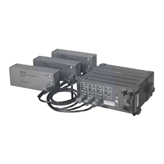
Chapter 1: Introduction PRC-BC4 The PRC-BC4 is a multiple battery charger designed to charge up to four BB-LA6 lead-calcium batteries simultaneously. The PRC-BC4 can use a 110 or 220 VAC power source (50 or 60 Hz); it can also use a 20 to 30V DC power source. -
Page 12: Specifications
1: Introduction Specifications PRC-BC4 Specifications Note: All specifications subject to change without notice or obligation. Characteristic Description General Input voltage 110/220 VAC or 20 to 30 VDC Input current 1A (max.) at 110 VAC 0.5A (max.) at 220 VAC 5A (max.) at 20 to 30 VDC... - Page 13 3.7 in. x 9.5 in. x 2.3 in. (9.4 cm x 24.2 cm x 5.8 cm.) CY-2562 Battery Box Specifications Characteristic Description Mechanical Weight 0.5 lbs. (0.23 kg) Size 3.0 in. x 4.0 in. x 11.0 in. (7.5 cm x 10 cm x 28 cm.) PRC-BC4-MS...
-
Page 15: Chapter 2: Installation
2.2.1 AC Input Power The PRC-BC4 can be configured for 110 or 220 VAC by opening the case and changing the connections on the power transformer. A label on the case indicates to what input voltage the transformer is set, however it is prudent to visually inspect the power transformer to verify what input voltage it is configured to accept (refer to Figure 2-2 on page 2-3). - Page 16 2: Installation 2. Place the PRC-BC4 so the front panel is faced away from you. Locate and remove the four captive screws that hold the front panel to the case (refer to Figure 2-1 below). CASE FRONT PANEL BOTTOM VIEW Figure 2-1 Captive and Chassis Screws 3.
- Page 17 AC FUSE Figure 2-2 Power Transformer Connections The PRC-BC4 is shipped with a molded AC power cable with a 3-wire plug and jack. It may be necessary to modify the plug to fit non-standard US AC receptacles. The following table provides the color codes for the conductors in the AC power cable.
- Page 18 CAUTION: Do not operate the PRC-BC4 when connected to both an AC and DC power source. The PRC-BC4 does not require any alignment or adjustment for normal operation. 2.2.3 Output Power The PRC-BC4 provides 12 VDC to up to four BB-LA6 lead-calcium batteries. PRC-BC4-MS...
-
Page 19: Chapter 3: Operation
Chapter 3: Operation The PRC-BC4 interface consists of four BB-LA6 battery external charging stations: three accessed from the front panel and a fourth from the rear of the chassis (refer to Figure 3-2 on page 3-2). CAUTION: Use the PRC-BC4 to charge BB-LA6 lead-calcium batteries only. - Page 20 3: Operation 3. Connect up to three DC charging cables (C991610) from the front panel charging station connectors to BB-LA6 batteries. Install an additional BB-LA6 battery to the rear of the PRC-BC4. To charge BB-LA6 batteries: 1. Turn the front panel...
-
Page 21: Chapter 4: Technical Description
This chapter provides a detailed description of the circuitry that the PRC-BC4 uses to charge BB-LA6 batteries. Input Power The PRC-BC4 derives input power for either an AC (110 or 220 VAC) or DC (20 to 30 VDC) power source. Both power sources are switched using the front panel switch. -
Page 22: Charging Circuit
4: Technical Description Charging Circuit The PRC-BC4 consists of four charging circuits with the three charging stations interfaced through the front panel and the fourth through the power connector on the back. Since all four charging circuits are identical, the following technical description only references charging circuit BATT 1. -
Page 23: Status Leds
(up to 1.1A) necessary to maintain this voltage. The BB-LA6 is now fully charged and can be left on the charger in this state for many years. If for some reason the BB-LA6 voltage drops below 12 VDC, the PRC-BC4 returns to the bulk charge state and repeats the charge cycle. - Page 24 4: Technical Description Figure 4-1 Charger Board Component Locations (738100 Rev. F) PRC-BC4-MS...
- Page 25 994003 NOTES: UNLESS OTHERWISE SPECIFIED 2.2uF/16V 1N6283A 1. RESISTANCE IS IN OHMS. 2. CAPACITANCE IS IN MICROFARADS. Datron World Communications, Inc. 3. DIODES ARE IN 1N4150 4. * DENOTES ON THE HEATSINK. 3055 Enterprise Ct. Vista CA 92081-8362 TEL:(760) 597-1500...
- Page 26 275104 “CAP, 0.1UF X7R 50V 10% RAD 0.1S” 230020 “CAP,2.2MF ELECT” 320103 “DIODE, 1N5400 3A 50V DO-201AD” 320002 “DIODE, 1N4148/1N4150 DO-35” 320002 “DIODE, 1N4148/1N4150 DO-35” 320002 “DIODE, 1N4148/1N4150 DO-35” 320002 “DIODE, 1N4148/1N4150 DO-35” 320103 “DIODE, 1N5400 3A 50V DO-201AD” PRC-BC4-MS...
- Page 27 “RES, 100K OHM, 1/4W, 5%, CF” 127104 “RES, 100K MF 1/4W 1% TH” 127203 “RES, 20K OHM 1/4W 1% MF” 124104 “RES, 100K OHM, 1/4W, 5%, CF” 124104 “RES, 100K OHM, 1/4W, 5%, CF” 127334 “RES, 330K OHM 1/4W 1% MF” PRC-BC4-MS...
- Page 28 330325 “IC, UC3906N” 330325 “IC, UC3906N” 330325 “IC, UC3906N” 330325 “IC, UC3906N” 330030 “IC,LIN,LM324N,DIP14,OP-AMP” 621004 “SOCKET, IC DIP-16 PIN” 621004 “SOCKET, IC DIP-16 PIN” 621004 “SOCKET, IC DIP-16 PIN” 621004 “SOCKET, IC DIP-16 PIN” 621005 “SOCKET, IC DIP-14 PIN” PRC-BC4-MS...
-
Page 29: Display Board
4: Technical Description Display Board The Display board includes all the , and LEDs FAULT CHARGING READY for each charging station on the PRC-BC4. Figure 4-3 Display Board Component Locations (738101 Rev. D) 4-10 PRC-BC4-MS... - Page 30 “LED, GREEN 28D T1-3/4” 320002 “DIODE, 1N4148/1N4150 DO-35” 320002 “DIODE, 1N4148/1N4150 DO-35” 320002 “DIODE, 1N4148/1N4150 DO-35” 320002 “DIODE, 1N4148/1N4150 DO-35” 320002 “DIODE, 1N4148/1N4150 DO-35” 320002 “DIODE, 1N4148/1N4150 DO-35” 320002 “DIODE, 1N4148/1N4150 DO-35” 610144 “HEADER,MLX,10PIN,.100” 310057 “XISTOR,NPN,PN2222A,TO92” 310057 “XISTOR,NPN,PN2222A,TO92” 310057 “XISTOR,NPN,PN2222A,TO92” PRC-BC4-MS 4-11...
- Page 31 “RES, 1.8K OHM, 1/4W, 5%, CF” 137272 “RES, 2.7K OHM 1/2W 5% CF” 124103 “RES, 10K OHM, 1/4W, 5%, CF” 137332 “RES,3.3K OHM 1/2W 1% MF” 124182 “RES, 1.8K OHM, 1/4W, 5%, CF” 330007 “IC, LM340T-12 VREG 12V 1A TO-220” 4-12 PRC-BC4-MS...
- Page 32 Functional Test Use the following test procedure to verify that the PRC-BC4 is working properly. If the PRC-BC4 fails one of the checks, refer to Table 5-1 on page 5-4. 5.1.1 Required Materials Use the following materials to perform the PRC-BC4 functional tests: •...
- Page 33 Measure the DC current. It should be 1.1A ±0.1A. The CHARGING LED for charging station should be lit when the ammeter and BATT 1 resistors are connected. Disconnect the ammeter and resistors. The LED should light READY up after a few seconds. PRC-BC4-MS...
- Page 34 Voltage Check 14.0 ±0.2 VDC. 1. Connect the 2.2 ohm resistor across the capacitor. Undervoltage Protection Circuit 2. Observe that the LED lights up after a few seconds. FAULT Check Repeat the previous checks for the other charging stations. PRC-BC4-MS...
- Page 35 This concludes the functional test. If the PRC-BC4 failed any of the previous steps, refer to “Troubleshooting” below. Troubleshooting 5.2.1 Index to Test Procedure If the PRC-BC4 fails a test procedure, Table 5-1 refers to a specific place in the troubleshooting procedure. Table 5-1 Troubleshooting Index Failed Test Section Troubleshooting Section “Charging Circuit Check”...
- Page 36 LED should now be lit. If more than one LED is lit, CHARGING refer to “Status LEDs” on page 5-8. 8. On pass transistor MJE2955, measure the voltage from the emitter to the base. If it is between 0.6 to 1.0 VDC, skip to step 9. PRC-BC4-MS...
- Page 37 (remove the AC power cable), and measure the resistance of these resistors to verify they are within 5% of their stated value. Turn the PRC-BC4 on and verify that the float charge voltage is within specification (13.3 VDC). If it is significantly out of specification, refer to “Current Source”...
- Page 38 5% of their stated value. 2. Turn the PRC-BC4 on and verify that the overcharge voltage is within specification (it should be 14.0 VDC), refer to “Current Source” on page 5-5 (step 8).
- Page 39 3. Measure the voltage on the op amp non-inverting input pin. It should be 1.2 to 1.5 VDC; if it is not, turn the PRC-BC4 off and measure the resistance to determine if it is shorted to ground. If there is no short,...
- Page 40 During the float charge state, measure the op amp output voltage. If it is not 2 VDC or less, measure the voltage on the inverting pin (pin 6). It should be greater than 1.5 VDC; if it is not, replace the charger IC. PRC-BC4-MS...
Need help?
Do you have a question about the PRC-BC4 and is the answer not in the manual?
Questions and answers