
Subscribe to Our Youtube Channel
Related Manuals for Datron PRC-PS


Summary of Contents for Datron PRC-PS
- Page 1 PRC-PS Power Supply/Battery Charger Operator/Technical Manual Manual Part No. PRC-PS-MS Release Date: November 2006 Revision: D...
- Page 2 Datron World Communications Inc. 995 Joshua Way, Suite A Vista, CA 92081, U.S.A. Phone: (760) 597-1500 Fax: (760) 597-1510 E-Mail: customerservice@dtwc.com www.dtwc.com...
- Page 3 Change Description Date of Revision Pages Description of Changes Revision Letter Affected 11/06 Update format and overall content. PRC-PS-MS...
- Page 5 Software, documentation, and All rights reserved. any copies of each to Datron. This Software is licensed “AS IS” and Datron provides a war- Datron World Communications, Inc. ranty that covers the media upon which the Software is embed- This manual, as well as the software described in it, is ded for a period of 30 days from receipt of the product.
- Page 6 Remedies: Buyer’s sole remedies and the entire liability of Datron are set forth above. In no event will Datron be liable to Buyer or any other person for any damages, including any incidental or consequential damages,...
-
Page 7: Table Of Contents
Table 5-2. Display Board Parts List (PRC-PS-DIS Rev. B2) ......5-20 Table 5-3. Front Panel Parts List (PRC-PS-FPL Rev. M) ......5-21... -
Page 9: Chapter 1: Introduction
PRC1099A transceiver, charge the BB-LA6 lead-calcium battery inside the transceiver and charge an additional BB-LA6 simultaneously. The PRC-PS can use a 50 or 60 Hz 110 VAC or 220 VAC (internally strapped) or a 20 Vdc to 30 Vdc power source. -
Page 10: Specifications
1: Introduction Specifications Note: All specifications subject to change without notice or obligation. 1.2.1 PRC-PS Specifications Characteristic Description General Input voltage 110/220 VAC or 20 to 30 Vdc (internally strapped) Input current 1A (max.) at 110 VAC 0.75A (max.) at 220 VAC 9A (max.) at 20 Vdc to 30 Vdc... - Page 11 9.4 cm x 24.2 cm x 5.8 cm (3.7 in. x 9.5 in. x 2.3 in.) 1.2.3 CY-2562 Battery Box Characteristic Description Specifications Mechanical Weight 0.23 kg (0.5 lbs.) Size 7.5 cm x 10 cm x 28 cm (3.0 in. x 4.0 in. x 11.0 in.) PRC-PS-MS...
-
Page 13: Chapter 2: Installation
• CY-2562 Battery box Power Configuration 2.2.1 The PRC-PS can be configured for 110 VAC or 220 VAC by opening the case AC Input and changing the connections on the power transformer. A label on the case Power indicates to what voltage level the transformer is set, however it is prudent to visually inspect the power transformer to verify what input voltage it is configured to accept. - Page 14 2: Installation Place the PRC-PS so the front panel is faced away from you. Locate and remove the four captive screws that hold the front panel to the case. CASE FRONT PANEL BOTTOM VIEW Figure 2-1. Captive and Chassis Screws Position the PRC-PS so the bottom side is facing you.
- Page 15 Green/yellow stripe 2.2.2 DC Input Power The PRC-PS also ships with a 2-wire DC input (14 AWG) cable. One end of the cable does not have a connector so that the appropriate connector can be added to connect to a DC power source. The power source must provide 20 Vdc to 30 Vdc and be capable of supplying 9A.
- Page 16 The PRC-PS does not require any alignment or adjustment for normal operation. 2.2.3 The PRC-PS is designed to provide 12 Vdc to the PRC1099A transceiver to DC Output power the radio and charge a BB-LA6 attached to the radio through the front Power panel J1 connector.
-
Page 17: Chapter 3: Operation
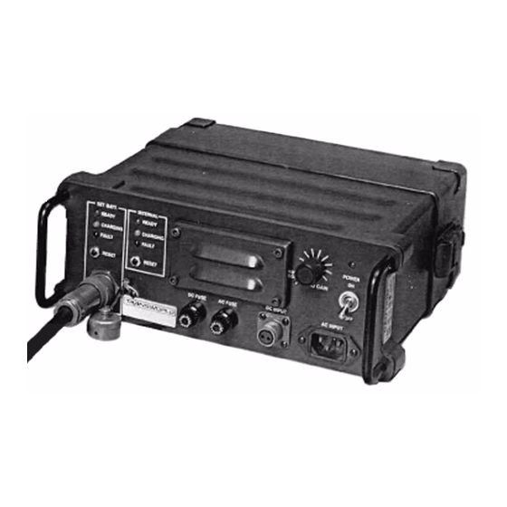
DC INPUT AC INPUT DC FUSE AC FUSE SET POWER Figure 3-1. PRC-PS Front Panel The PRC-PS front panel provides the following interfaces and controls. Interface or Control Description SET BATT Charging Provides 12.5 Vdc to power the PRC1099A Station and charge the BB-LA6 installed in the PRC1099A. - Page 18 Attempting to recharge lithium, magnesium or other battery types may result in explosion or release of toxic material. To set up the PRC-PS for powering the PRC1099A and charging BB-LA6 batteries: Make sure the power transformer is configured correctly for the intended power source.
- Page 19 Required Action CHARGING Battery is charging None. normally. READY Battery is fully charged. Remove battery. The battery may be left connected to the charger. BB-LA6 PRC1099A PRC-PS BB-LA6 C991608 C991609 24 Vdc source 115/230 Vac source Figure 3-2. Charging Configuration PRC-PS-MS...
-
Page 21: Chapter 4: Theory Of Operation
PRC1099A and charge BB-LA6 batteries. Input Power The PRC-PS derives input power for either an AC (115 VAC or 230 VAC) or DC (20 Vdc to 30 Vdc) power source. The front panel POWER switch controls both power input lines. - Page 22 10 from ground (in the bulk charge state) which places R18 in parallel with R19, to a high impedance that places R18 in series with R19, shifting the Vcutoff to 13.3V. The PRC-PS uses PRC-PS-MS...
-
Page 23: Status Leds
BB-LA6 is now fully charged and can be left on the charger in this state for extended periods of time. If for some reason the BB-LA6 voltage drops below 12 Vdc, the PRC-PS returns to the bulk charge state and repeats the charge cycle. -
Page 24: Dc Power Supply
CHARGE and READY LEDs. DC Power Supply In addition to charging BB-LA6 batteries, the PRC-PS provides 14 Vdc to the PRC1099A. The power supply circuitry uses an adjustable 5 Vdc reference diode D2 to control the output voltage. Series resistors R2 and R3 forward-bias the diode and R4 adjusts the reference voltage which is typically about 4.6 Vdc. -
Page 25: Chapter 5: Maintenance
Use the DC power supply to charge the electrolytic capacitor between 6 Vdc and 13 Vdc. Remove the battery from the back of the PRC-PS. Use the clip jumpers to attach the rear panel power connector J4 to the capacitor as if it were a BB-LA6. - Page 26 Measure the DC current. It should be 1.1A ±0.1A. The CHARGING LED for the INTERNAL charging station should be lit when the ammeter and resistors are connected. Disconnect the ammeter and resistors. The READY LED should light up after a few seconds. PRC-PS-MS...
- Page 27 1. Measure the DC voltage across the 82 ohm resistor. It should be Voltage Check 14.0 Vdc ±0.2 Vdc. Undervoltage 1. Connect the 2.2 ohm resistor across the capacitor. Protection Circuit Observe that the FAULT LED lights up after a few seconds. Check PRC-PS-MS...
- Page 28 RX Audio Connect the C991608 cable to the SET POWER connector (J1) on the PRC-PS front panel. Carefully insert a short bus wire (18 AWG) into pin A and another one into pin E on the C991608 cable connector. Repeat the previous checks.
- Page 29 C (PTT) on the SET POWER connector and verify the speaker audio shuts off. Remove the ground from pin C and verify the speaker audio comes back This concludes the functional test. If the PRC-PS failed any of the previous steps, refer to the Troubleshooting Index table on page 5-6.
- Page 30 5: Maintenance Troubleshooting 5.2.1 The following table refers the technician to a specific place in the Index to Test troubleshooting procedure if the PRC-PS fails the indicated step in the test Procedure procedure. Table 5-1. Troubleshooting Index Failed Test Section...
- Page 31 If it is not 0.25 Vdc ± 0.02 Vdc, refer to the Status LEDs section on page 5-10. Turn off the power and measure the resistance of the 0.22 ohm resistor R23. If it is not within 5% tolerance, replace the resistor. PRC-PS-MS...
- Page 32 Overcharge Voltage Check section on Voltage page 5-3 if the overcharge voltage is not set at 14.0 Vdc. Turn the PRC-PS on for the following checks. 1. R19 (20 k ohms), R22 (100 k ohms) and R18 (330 k ohms) are 1% resistors that set the overcharge voltage.
- Page 33 AC Power Supply section on page 5-9. AC Power Supply This section assumes a problem with the AC input power circuit. Turn the PRC-PS off for the following checks. CAUTION: Always turn the power off and remove the power source before making any resistance measurements.
- Page 34 This section assumes the status LEDs are either not lighting or lighting at the wrong time. 1. Turn on the PRC-PS. If more than one LED lights up at one time, turn the PRC-PS off and measure the resistance across each diode on the display board.
- Page 35 J1 pin C. Measure the DC voltage at pin C. If it is not 12.5 Vdc, measure the resistance across diode D9. If it is okay, replace transformer K1. Measure the AC voltage at the output of U5 pin 4. If it is not 2.8 Vrms, replace capacitor C15. PRC-PS-MS 5-11...
- Page 37 FAULT CHARGING READY FAULT CHARGING READY Schematic Diagram (994004 Rev. K) 5-13 3030 Enterprise Ct. Vista, CA 92083 (760)597-3777 Title: Schematic PRC-PS BATTERY CHARGER PRC-PS-MS Drawn: Date: Size: Drawing Number: Rev: A. MARTINEZ 994004 Appr: Date: File: 994004K.Sch Date: 26-Oct-2006...
- Page 38 5: Maintenance Figure 5-5. Charger Board Component Locations (738105 Rev. F) PRC-PS-MS 5-15...
- Page 39 5: Maintenance Note: The charger board schematic diagram is included in the PRC-PS Mainframe Schematic Diagram on page 5-13. Table 5-1. Charger Board Parts List (PRC-PS-CHG Rev. K) Designator Part Number Description 275104 CAP, 0.1UF X7R 50V 10% 0.1LS 275104 CAP, 0.1UF X7R 50V 10% 0.1LS...
- Page 40 5: Maintenance Table 5-1. Charger Board Parts List (PRC-PS-CHG Rev. K) Designator Part Number Description 320002 DIODE, 1N4148/1N4150 DO-35 320103 DIODE, 1N5400 3A 50V DO-201AD 320002 DIODE, 1N4148/1N4150 DO-35 320002 DIODE, 1N4148/1N4150 DO-35 320103 DIODE, 1N5400 3A 50V DO-201AD 320002...
- Page 41 5: Maintenance Table 5-1. Charger Board Parts List (PRC-PS-CHG Rev. K) Designator Part Number Description 127203 RES,20K 1/4W 1% FILM MTL 124104 RES,100K 1/4W 5% CARBON FILM 124104 RES,100K 1/4W 5% CARBON FILM 127104 RES,100K 1/4W 1% FILM MTL 124472 RES,4.7K 1/4W 5% CARBON FILM...
- Page 42 5: Maintenance Figure 5-6. Display Board Component Locations (738106 Rev. A) PRC-PS-MS 5-19...
- Page 43 5: Maintenance Note: The charger board schematic diagram is included in the PRC-PS Mainframe Schematic Diagram on page 5-13. Table 5-2. Display Board Parts List (PRC-PS-DIS Rev. B2) Designator Part Number Description 320002 DIODE, 1N4148/1N4150 DO-35 320415 LED,RED 320417 LED,YELLOW...
- Page 44 5: Maintenance Table 5-3. Front Panel Parts List (PRC-PS-FPL Rev. M) Designator Part Number Description 210104 CAP,.1MF 25V DISC 275104 CAP, 0.1UF X7R 50V 10% 0.1LS 320211 DIODE, 1N6283A 28V TVS DO-204 320416 LED,GREEN 630001 HOLDER FUSE POST 630001 HOLDER FUSE POST...
Need help?
Do you have a question about the PRC-PS and is the answer not in the manual?
Questions and answers