Table of Contents
Advertisement
Quick Links
RESISTRON
RES-409
Operating
instructions
Important features
•
Microprocessor technology
•
Complete control via CAN-Bus interface (CAN 2.0A according ISO 11898)
Remark: CANopen is not supported
•
Automatic zero calibration (AUTOCAL)
•
Automatic optimization (AUTOTUNE)
•
Automatic configuration of the secondary voltage and current ranges
(AUTORANGE, as of February 2007)
•
Automatic phase angle compensation (AUTOCOMP, as of February 2007)
•
Automatic frequency adjustment
•
Large current and voltage range
•
0...10VDC analog output for ACTUAL temperature
•
Additional 24VDC control signals for START 0 (Set 0) and START 1 (Set 1)
(as of February 2007)
•
Alarm function with fault diagnosis
•
Heatsealing band alloy and temperature range selectable
•
Booster connection as standard (as of February 2007)
Industrie-Elektronik GmbH
Gansäcker 21
D-74321-Bietigheim-Bissingen (Germany)
GB
Tel: +49/(0)7142/7776-0
Fax: +49/(0)7142/7776-19
E-Mail:
info@ropex.de
Internet:
www.ropex.de
Data subject to change
Advertisement
Table of Contents

Related Manuals for Resistron ROPEX RES-409

Summary of Contents for Resistron ROPEX RES-409
- Page 1 RESISTRON RES-409 Operating instructions Important features • Microprocessor technology • Complete control via CAN-Bus interface (CAN 2.0A according ISO 11898) Remark: CANopen is not supported • Automatic zero calibration (AUTOCAL) • Automatic optimization (AUTOTUNE) • Automatic configuration of the secondary voltage and current ranges (AUTORANGE, as of February 2007) •...
-
Page 2: Table Of Contents
Contents Safety and warning notes ....3 Controller functions ....25 Use . -
Page 3: Safety And Warning Notes
Safety and warning notes This RESISTRON temperature controller The RESISTRON temperature controller must be set manufactured according to DIN EN 61010-1. In the and coded according to the temperature coefficient of course of its manufacture it passed through quality the heatsealing band. -
Page 4: Line Filter
ROPEX. Application This RESISTRON temperature controller is an integral The controller is most commonly used for impulse- part of the "Series 400", the outstanding feature of heatsealing PE films in:... -
Page 5: Principle Of Operation
Principle of operation The use of RESISTRON temperature controllers • Increased machine capacity results in: • Extended life of the heatsealing bands and teflon coatings • Repeatable quality of the heatseals under any conditions • Simple operation and control of the sealing process... -
Page 6: Description Of The Controller
(0…300°C, 0…500°C etc.). The RESISTRON temperature controller RES-409 is The compact design of the RESISTRON temperature equipped with a CAN-Bus interface type CAN 2.0A controller RES-409 and the plug-in connections make according ISO 11898 (Remark: CANopen is not this controller easy to install. -
Page 7: Modifications (Mods)
( ROPEX Application Report). Communication interface CI-USB-1 Interface for connecting a RESISTRON temperature controller with diagnostic inter- face (DIAG) to the PC (USB port). Associated PC visualization software for dis- playing setting and configuration data, and for recording SET and ACTUAL tempe- ratures in real time. -
Page 8: Technical Data
Technical data Technical data Type of construction Housing for installation in the electrical cabinet Snaps onto a standard top hat rail (DIN TS35 rail, 35 mm) acc. to DIN EN 50022 Dimensions: 90 x 75mm; height: 135mm (incl. terminals) Line voltage All controllers manufactured as of February 2007: 115VAC version: 110VAC -15%…120VAC +10% (equivalent to 94…132VAC) 230VAC version: 220VAC -15%…240VAC +10% (equivalent to 187…264VAC) - Page 9 Technical data Heatsealing band All controllers manufactured as of February 2007: type and temperature The temperature range and temperature coefficient settings can also be specified range in the ROPEX visualization software ( section 10.12 "Diagnostic interface / visualization software (as of February 2007)" on page 43) in addition to using the rotary coding switch (see below) or the CAN interface: Temperature range: 200°C, 300°C, 400°C or 500°C...
- Page 10 Technical data Ambient +5…+45°C temperature Degree of protection IP20 Installation If several controllers are installed on one top hat rail (DIN TS35 rail), a clearance of at least 20mm should be allowed between them. The moving clip required for fastening must be facing down for mounting on a horizontal top hat rail.
-
Page 11: Dimensions
47Hz to 63Hz. 3. Install the RESISTRON temperature controller on a Installation procedure standard top hat rail (DIN TS35 rail according to DIN EN 50022) in the electrical cabinet. If several... -
Page 12: Installation Steps
6. Make sure that the wiring conforms to all relevant provided in section 8.2 "Installation steps" on national and international installation regulations. page 12 must be additionally heeded. 5. Connect the RESISTRON temperature controller to the CAN master using a cable according to IEC 947-5-2. Installation steps... -
Page 13: Power Supply
( ROPEX Application Report). Short wires Do not run the filter supply wires (line side) parallel to the filter output wires (load side). ROPEX RESISTRON temperature controller belonging to the temperature controller 4xx Series. Relay Kb Load break (all-pole), e.g. in combination with the alarm output of the temperature controller. -
Page 14: Line Filter
You can find the exact specification of the line filter in To comply with EMC directives – corresponding to the ROPEX Application Report calculated for your par- EN 50081-1 and EN 50082-2 – RESISTRON control ticular heatsealing application. loops must be operated with line filters. -
Page 15: Wiring Diagram (Standard)
Montage und Installation Wiring diagram (standard) CAN bus Line filter LF-xx480 Plug assignment RES-409 (RES-409) LINE 3 = blue (also with MOD 01) 4 = black 1 = brown CAN bus Plug 1 3-pole CAN bus Controller Bus GND electrically isolated CAN bus Plug 2... -
Page 16: Wiring Diagram With Booster Connection (Mod 26)
Montage und Installation Wiring diagram with booster connection (MOD 26) CAN bus Line filter LF-xx480 Plug assignment RES-409 (RES-409) LINE 3 = blue (also with MOD 01) 4 = black Booster 1 = brown CAN bus Plug 1 CAN bus 3-pole Controller Bus GND... -
Page 17: Startup And Operation
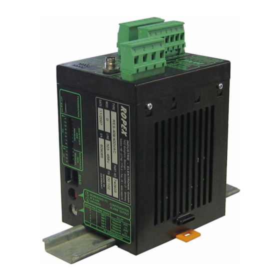
Startup and operation Startup and operation View of the controller CAN plug Terminals LEDs Coding switch for CAN parameters Plug-in jumper Nameplate Coding switch RES-409 Page 17... -
Page 18: Controller Configuration
Startup and operation Controller configuration range from 30A to 500A. If the voltage and/or current are outside the permissible range, a detailed error message appears controller ( see The controller must be switched off in order section 10.16 "Error messages" on page 45). to configure the coding switches and plug-in jumpers. - Page 19 Startup and operation 9.2.2 Configuration of the rotary coding switch for the temperature range and alloy (as of January 2007) Switch Temp. Temp. Band position range coefficient alloy 300°C 1100ppm/K e.g. Alloy-20 300°C 780ppm/K e.g. Alloy L 500°C 1100ppm/K e.g. Alloy-20 500°C 780ppm/K e.g.
- Page 20 Startup and operation 9.2.4 Configuration of the CAN interface The CAN BUS-interface of the RES-409 supports CAN 2.0A according ISO 11898. The CAN interface of the RES-409 is configured with CANopen is not supported. DIP switches. The baud rate and some of the identifiers can be set.
- Page 21 Startup and operation 9.2.5 DIP switches for setting the baud rate All controllers manufactured as of February 2007: All controllers manufactured up to January 2007: The following baud rates can be set for the CAN bus Various baud rates can be set for the CAN bus with DIP with the four-pole DIP switch: switches 6 to 8.
- Page 22 Startup and operation 9.2.6 DIP switches for setting the identifiers A new DIP switch setting does not take effect until the next time the controller is switched All controllers manufactured as of February 2007: maximum of 253 different controllers can be addressed The 8-pole DIP switch determines the 8 high bits of the in a CAN network.
-
Page 23: Heatsealing Band
We shall therefore only All power supply leads must be disconnected from the refer to a few of the most important physical and RESISTRON temperature controller in order to replace electrical properties. the heatsealing band. - Page 24 Startup and operation 2. The supply voltage specified on the nameplate of 7. Activate the AUTOCAL function by sending CAN the controller must be identical to the line voltage message address 4, value 5 while the heatsealing that is present in the plant or machine. The line band is still cold.
-
Page 25: Controller Functions
(green LED) measurement mode. In control NETWORK STATUS MODUL STATUS mode, luminous intensity is proportional to heating current. AUTOCAL Remains lit for duration of RESISTRON (yellow LED) AUTOCAL process. RES- 409 Temperature controller ROPEX µC PWR OK Lit if internal 5VDC power... -
Page 26: Can Protocol
Controller functions In addition to the functions shown in the diagram by the LEDs. These states are described in detail in the above, various controller operating states are indicated table below: Blinks slowly (1Hz) Blinks fast (4Hz) Lit continuously AUTOCAL requested but AUTOCAL Indicates undervoltage function is locked... -
Page 27: Receiving Can Messages
Controller functions 10.3 Receiving CAN messages The complete command set of the RES-409 is shown in the table below: Address Value Meaning (hex) (dec) 0000 0…T Store set point 0 (in °C) 0001 0…T Store set point 1 (in °C) 0002 0…T Store set point 2 (in °C) - Page 28 Controller functions Address Value Meaning (hex) (dec) 0004 Query set point 0 (in °C) Query set point 1 (in °C) Query set point 2 (in °C) Query set point 3 (in °C) Query controller status Run "AUTOCAL" function Run "Reset" after fault Query current actual value Query controller number, part 1 Query controller number, part 2...
- Page 29 Controller functions Address Value Meaning (hex) (dec) 0008 Store alloy/range (heatsealing band alloy TCR/temperature range): TCR = 1100ppm/K, max. temperature range 200°C TCR = 1100ppm/K, max. temperature range 300°C TCR = 1100ppm/K, max. temperature range 400°C TCR = 1100ppm/K, max. temperature range 500°C TCR = 3500ppm/K, max.
- Page 30 Controller functions Address Value Meaning (hex) (dec) 0013 AUTOCOMP: OFF AUTOCOMP: ON AUTOCOMP: AUTO (as of software revision 102) ( section 10.8 "Automatic phase compensation (AUTOCOMP, as of February 2007)" on page 40) 0014 Temperature range 200°C Temperature range 300°C Temperature range 400°C Temperature range 500°C (applies if address 0008 contained the value 11 (dec))
- Page 31 Controller functions 10.3.2 START / STOP command The fault output is switched if a "START" command (or the "START" signal) is activated while a warning "START" signal message with error codes 8…12 (as of February 2007 also: 104…106, 111…114, 211, 302, 303) is displayed A "START"...
- Page 32 Controller functions The "START" signal (START 1) for set point 1 is If the temperature of the heatsealing band varies on activated by applying a 24VDC signal at terminals 7+8. controllers manufactured as of February 2007, the "AUTOCAL" function is run a maximum of three times. 24VDC If the function still cannot be executed successfully, an RES-409...
-
Page 33: Sending Can Messages
Controller functions If a START or STOP command is received between the The scale of the analog output for the ACTUAL "AUTOCAL" request and the actual start of the temperature is dependent on the selected temperature "AUTOCAL" function, the "AUTOCAL" request is range: canceled again and the START or STOP command is executed instead. - Page 34 Controller functions Address Value Meaning (hex) (dec) 0000 0…T Current set point 0 (in °C) 0001 0…T Current set point 1 (in °C) 0002 0…T Current set point 2 (in °C) 0003 0…T Current set point 3(in °C) 0004 -20…T Current actual value (in °C) 0005 (...
- Page 35 Controller functions Address Value Meaning (hex) (dec) 001B 0…15 Current controller type (RES-409 = value 7) RES-409 Page 35...
- Page 36 Controller functions 10.4.1 Controller status the error message ( section 10.16 "Error messages" on page 45). The controller status is sent on request. It contains all The controller status is coded as follows: important information about the controller. If a fault occurs, it can be accurately diagnosed with the help of Bit no.
- Page 37 Controller functions 10.4.2 Acknowledgment message command. This message contains the current actual value and the most important status information: The RES-409 automatically sends an acknowledgment message (address 9) after every START/STOP Bit no. Name Meaning 0…8 Actual value Current actual value (in °C) Sign Sign of the actual value.
-
Page 38: Temperature Meter (Actual Value Output)
Bereich 0 - 300°C °C RESISTRON temperature controller in a CAN network. It is divided into two parts, in order to comply with the message format ( section 10.2 "CAN protocol" on page 26). -
Page 39: Hold Mode
Controller functions therefore always be used ( section 5 "Accessories an additional 2 seconds at the end of a heating and modifications" on page 6). phase if it is queried via the CAN interface. The meter only facilitates SET-ACTUAL ACTUAL temperature is then transferred again in comparisons but also enables other criteria such as the real time until the end of the next heating phase. -
Page 40: Measuring Impulse Length (As Of February 2007)
Controller functions 10.7 Measuring impulse length AUTOCAL <2.0s (as of February 2007) command The length of the measuring impulses generated by the controller can be set with this parameter (CAN message address 12). It may be necessary to set a measuring impulse that is longer than the default 1.7ms for certain applications (... -
Page 41: Temperature Monitoring / "Temperature Ok" Bit (As Of February 2007)
Controller functions 7. The upper and lower tolerance band limits can also AUTOCAL be set independently of one another on controllers command manufactured as of February 2007 (CAN message "AC" addresses D and E). The following settings are possible: 1. "Off" "Temperature OK"... -
Page 42: Temperature Diagnosis (As Of February 2007)
Controller functions ACTUAL temp. Actual value Set+ Set+ upper upper Set+ Set+ lower lower Time "Temperature OK" in controller status Time Time Fault 10.10 Temperature diagnosis If the temperature diagnosis is not activated by the time (as of February 2007) the "START"... -
Page 43: Diagnostic Interface / Visualization Software (As Of February 2007)
Controller functions (304) is indicated and the fault relay is switched ROPEX visualization software using the ROPEX ( section 10.16 "Error messages" on page 45). CI-USB-1 communication interface. ACTUAL temp. 95% of Set Time- Only a ROPEX communication interface is allowed to be connected to the diagnostic interface. -
Page 44: Undervoltage Detection (As Of February 2007)
Controller functions 10.14 Undervoltage detection February 2007 also: 101…103, 107, 108, 201…203, 307, 308, 801, 9xx). (as of February 2007) Also in instances 1 and 2 if a "START" command is simultaneously sent. Trouble-free operation of the temperature controller is As a rule, this refers to an external wiring fault. -
Page 45: Error Messages
Controller functions An error message can only be reset by The table below shows how the analog voltage values sending "RESET" command at the actual value output are assigned to the faults that switching the controller off and then on again. have occurred. - Page 46 Controller functions Page 46 RES-409...
- Page 47 Controller functions RES-409 Page 47...
- Page 48 Controller functions Page 48 RES-409...
- Page 49 Controller functions RES-409 Page 49...
-
Page 50: 10.17 Fault Areas And Causes
Controller functions 10.17 Fault areas and causes Temperature controller HARDWARE The table below explains the possible fault causes. Fault area Explanation Possible causes Load circuit interrupted after U - Wire break, heatsealing band break - Contact to heatsealing band is defective pickoff point ... -
Page 51: Factory Settings
Internal controller fault - Hardware fault (replace controller) - Plug-in jumper for alarm output not connected or incorrectly connected Factory settings The RESISTRON temperature controller RES-409 is configured in the factory as follows: DIP switches = 6…60VAC = 30…100A secondary voltage... -
Page 52: Maintenance
Maintenance Measuring impulse Measuring impulse length: 1.7ms length Temperature Temperature diagnosis: OFF diagnosis Heatup timeout Heatup timeout: OFF Output 1 „Temperature OK“-Bit: aktive if T Hold mode Hold mode: OFF DIP switch As of February 2007: for identifier and Identifier = 0 baudrate Baudrate = AutoBaud Termination = ON... -
Page 53: How To Order
How to order How to order Contr. RES - 409 / . . . VAC 115: Power supply 115VAC, Art. No. 740901 230: Power supply 230VAC, Art. No. 740902 400: Power supply 400VAC, Art. No. 740903 Scope of supply: Controller includes connector plug-in parts (without current transformer) Modification MOD . - Page 54 How to order Booster B- . . . 400 075: Max. pulse load 75A, 400VAC, Art. No. 885301 100: Max. pulse load 100A, 400VAC, Art. No. 885304 Page 54 RES-409...
-
Page 55: Index
Index Index Heatsealing band type Heatup timeout ACTUAL temperature Hold mode Actual value output Alarm relay Alloy Ambient temperature Impulse heatsealing method Analog temperature meter Impulse transformer Application Installation Application Report Installation procedure AutoBaud Installation regulations AUTOCAL AUTOCOMP Automatic baud rate detection Line filter Automatic phase compensation Line frequency... - Page 56 Index Temperature coefficient Temperature control Undervoltage detection Temperature meter Temperature monitoring Temperature OK bit Visualization software Temperature range Temperature reached bit Transformer Wiring Type of construction Page 56 RES-409...
Need help?
Do you have a question about the ROPEX RES-409 and is the answer not in the manual?
Questions and answers