Table of Contents

Related Manuals for WattNode WNC-3Y-208-MB


Summary of Contents for WattNode WNC-3Y-208-MB
- Page 1 ® Installation and Operation Manual ● WNC-3Y-208-MB ● WNC-3Y-400-MB ● WNC-3Y-480-MB ● WNC-3Y-600-MB ● WNC-3D-240-MB ● WNC-3D-400-MB ● WNC-3D-480-MB Continental Control Systems Rev 1.16c http://www.ccontrolsys.com (M7)
- Page 2 FAX: (303) 444-2903 E-mail: techsupport@ccontrolsys.com Web: http://www.ccontrolsys.com WattNode is a registered trademark of Continental Control Systems, LLC. FCC Information This equipment has been tested and complies with the limits for a Class B digital device, pursu- ant to part 15 of the FCC Rules. Operation is subject to the following two conditions: (1) This device may not cause harmful interference, and (2) this device must accept any interference received, including interference that may cause undesired operation.
-
Page 3: Table Of Contents
Measurement Troubleshooting ....................... 26 Other Fixed Pattern ......................... 26 Modbus Communication Diagnostics .................... 28 Operating Instructions ......................31 Quick Start .............................31 WattNode Basic Configuration ....................31 Verify Operation ........................31 Modbus Communication ....................... 32 Modbus Functions ........................32 Measurement Overview ......................32 Report Slave ID ........................33 Modbus Register Lists ........................ - Page 4 Advanced Register List - Floating Point ................... 36 Advanced Register List - Integer ....................37 Configuration Register List ...................... 38 Communication Register List ....................39 Diagnostic Register List ......................39 Option Information Registers ....................40 Custom Register Map ......................40 Basic Registers ..........................41 Energy Registers ........................41 Power Registers ........................41 Voltage Registers ........................
-
Page 5: Overview
9,600 and 19,200 baud, and rates from 1,200 to 38,400 baud can be configured. The meter uses the industry standard Modbus RTU (binary) communication protocol, allowing up to 127 devices per RS-485 subnet. The WattNode meter can auto-detect RS-485 polarity on properly biased networks, simplifying installation. -
Page 6: Current Transformers
● Option TTL - Provide 5V TTL UART I/O in place of RS-485. Current Transformers The WattNode meter uses solid-core (toroidal), split-core (opening), and bus-bar current trans- formers (CTs) with a full-scale voltage output of 0.333 Vac. Split-core and bus-bar CTs are easier to install without disconnecting the circuit being measured. -
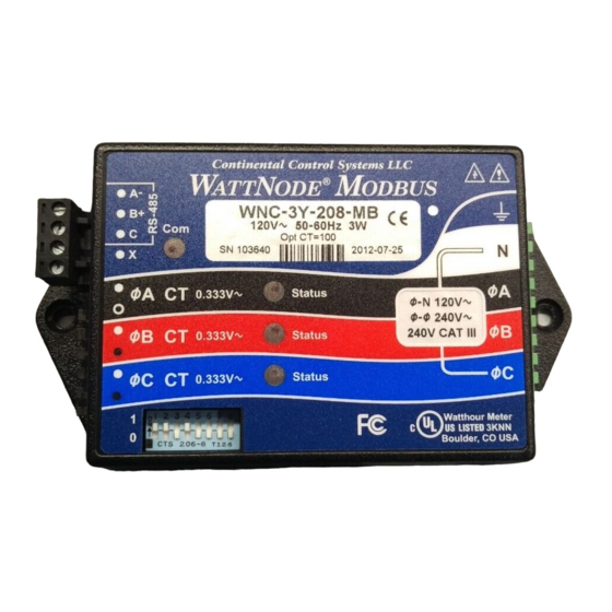
Page 7: Front Label
G: Line voltage measurement ratings. This block lists the nominal line-to-neutral “Ø-N 120V~” voltage, line-to-line “Ø-Ø 240V~” voltage, and the rated measurement voltage and category “240V CAT III” for this WattNode model. See the Specifications (pg 56) for more informa- tion about the measurement voltage and category. -
Page 8: Symbols
W: Maximum rated power. This is the maximum power consumption (watts) for this model. X: Manufacture date. This is the date of manufacture for this WattNode meter. Y: Caution, risk of electrical shock. This symbol indicates that there is a risk of electric shock when installing and operating the meter if the installation instructions are not followed correctly. -
Page 9: Installation
0.333 Vac (333 millivolts AC) at rated current. Do not use current output (ratio) CTs such as 1 amp or 5 amp output CTs: they will destroy the WattNode meter and may create a shock hazard. See Current Transformers (pg 60) for CT maximum input cur- rent ratings. -
Page 10: Electrical Service Types
3 Phase 4 Wire Delta 240/415/480V with neutral *The wire count does NOT include ground. It only includes neutral (if present) and phase wires. Table 1: WattNode Models Single-Phase Two-Wire with Neutral This configuration is most often seen in homes and offices. The two conductors are neutral and line. -
Page 11: Single-Phase Three-Wire (Mid-Point Neutral)
Figure 3: Single-Phase Three-Wire Connection Recommended WattNode Models The following table shows the WattNode models that can be used. If neutral may or may not be present, you should use the WNC-3D-240-MB (see Single-Phase Two-Wire without Neutral below). If neutral is present, it must be connected for accurate measurements. If phase B may not be present, you should use the WNC-3Y-208-MB (see Single-Phase Two-Wire with Neutral above). -
Page 12: Single-Phase Two-Wire Without Neutral
208 - 240 Vac WNC-3D-240-MB If neutral is available, you may also use the WNC-3Y-208-MB model. If you use the WNC-3Y-208-MB, you will need to hook up the meter as shown in section Single-Phase Three- Wire (Mid-Point Neutral) and connect neutral. You will need two CTs. -
Page 13: Three-Phase Four-Wire Wye
Note: you may also use the following delta WattNode models to measure three-phase four-wire wye circuits. The only difference is that delta WattNode models are powered from ØA and ØB, rather than N and ØA. If neutral is present, it must be connected for accurate measurements. -
Page 14: Three-Phase Three-Wire Delta Without Neutral
CTs are connected to matching phases. For these models, the meter is powered from the ØA and ØB (phase A and phase B) terminals. Note: all delta WattNode models provide a neutral connection N, which allows delta WattNode models to measure both wye and delta configurations. -
Page 15: Mounting
38 mm (1.50") High Figure 7: WattNode Meter Dimensions The WattNode meter has two mounting holes spaced 127 mm (5.0 in) apart (center to center). These mounting holes are normally obscured by the detachable screw terminals. Remove the screw terminals by pulling outward while rocking from end to end. The meter or Figure 7 may be... -
Page 16: Selecting Current Transformers
CT is the labeled rating divided by the number of times that the wire passes through the CT. If you are using the measurement phases of the WattNode (ØA, ØB, and ØC) to measure dif- ferent circuits, you can use CTs with different rated current on the different phases. Instead of setting one CtAmps value for all phases, you can use different values for each phase: CtAmpsA, CtAmpsB, and CtAmpsC. -
Page 17: Connecting Current Transformers
140% 120% 100% Crest Factor Figure 8: Maximum CT Current vs. Crest Factor You frequently won’t know the crest factor for your load. In this case, it’s generally safe to assume the crest factor will fall in the 1.4 to 2.5 range and select CTs with a rated current roughly 150% of the expected RMS current. -
Page 18: Circuit Protection
● The WattNode meter has an earth connection, which should be connected for maximum accuracy. However, this earth connection is not used for safety (protective) earthing. -
Page 19: Connecting Voltage Terminals
Figure 9: WattNode LED Overvoltage Warning The WattNode meter is powered from the voltage inputs: ØA (phase A) to N (neutral) for wye “-3Y” models, or ØA to ØB for delta “-3D” models. If the meter is not receiving at least 80% of the nominal line voltage, it may stop operating. -
Page 20: Baud Rate
This can be useful if you cannot communicate and need to return the meter to a known state. Option AD The WattNode Modbus meter can be ordered from the factory with the Modbus address pre- programmed to any value from 1 to 247 using Option AD=xxx where xxx is the desired address. - Page 21 “B+” terminal. Without bias resistors, the bus can float and noise can appear as bogus data. The WattNode meter uses an RS-485 failsafe transceiver that eliminates the need for bias resis- tors except in noisy environments. Furthermore, many RS-485 PC interfaces include internal bias resistors, so it is rare to need to add bias resistors.
-
Page 22: Installation Summary
Wiring Once you’ve planned the network and strung the cable, you can connect the WattNode meters. ● The Modbus terminals (A-, B+, C, and X) are completely isolated (4500 Vac RMS isolation) from dangerous voltages, so you can connect them with the meter powered. They are also isolated from the meter’s earth ground and neutral connections. -
Page 23: Installation Led Diagnostics
Installation LED Diagnostics The WattNode meter includes multi-color power diagnostic LEDs for each phase to help verify correct operation and diagnose incorrect wiring. The LEDs are marked “Status” on the label. The following diagrams and descriptions explain the various LED patterns and their meanings. The A, B, and C on the left side indicate the phase of the LEDs. - Page 24 ● In some cases, this can also occur if the CT wires are connected to the wrong inputs, such as if the CT wires for phases B and C are swapped. Note: if all three LEDs are flashing red and they always turn on and off together, like the diagram for Low Line Voltage below, then the meter is experiencing an error or low line voltage, not nega- tive power.
- Page 25 ● In some cases, particularly for a circuit with no load, this may be due to electrical noise. This is not harmful and can generally be disregarded, provided that you are not seeing substantial measured power when there shouldn’t be any. Try turning on the load to see if the erratic flashing stops.
-
Page 26: Measurement Troubleshooting
(or line-to-ground for delta circuits). You should check the actual voltages present at the WattNode meter with a DMM (multimeter) if possible. The WattNode Modbus meter does not measure line-to-line voltages, so you will not be able to verify them. - Page 27 CT leads are long, interference can occur. Try moving the WattNode meter at least three feet (one meter) away from any VFDs. Use short CT leads if possible. NEVER install the meter downstream of a VFD: the varying line frequency and extreme noise will cause problems! ○...
-
Page 28: Modbus Communication Diagnostics
200 milliseconds. Other Modbus Activity Yellow If the WattNode meter sees packets on the bus addressed to other devices, it will 0.2s light the LED yellow for 200 milliseconds or longer if the packet duration is longer than 200 milliseconds. - Page 29 ● It sees unexpected data on the RS-485 bus when it is preparing to respond to a command. This generally is due to another WattNode meter with the same address responding first, although it could also be extra bytes from the Modbus master or another device.
- Page 30 ○ ErrorStatus 19, 20, 72, 79, 80, 215: Internal hardware failure. ○ ErrorStatus 67: Calibration data lost. The WattNode meter will report a slave device failure until it is calibrated. ● 06 - Slave device busy ○...
-
Page 31: Operating Instructions
Modbus Communication Diagnostics (pg 28). WattNode Basic Configuration Out of the box, the WattNode meter is ready to start measuring as soon as the current trans- former rated amps (CtAmps) are configured (the default value is five amps). -
Page 32: Modbus Communication
However, very few devices follow this part of the Modbus standard, so the WattNode meter defaults to 8 data bits, no parity, and one stop bit instead. If your application requires even parity, order Option EP or change the parity using the ParityMode register. -
Page 33: Report Slave Id
Table 7: Report Slave ID Response The standard values for the Additional Data field follow: WattNode Model Response String WNC-3Y-208-MB Continental Control Systems LLC, WattNode MODBUS, WNC-3Y-208-MB WNC-3Y-400-MB Continental Control Systems LLC, WattNode MODBUS, WNC-3Y-400-MB WNC-3Y-480-MB Continental Control Systems LLC, WattNode MODBUS, WNC-3Y-480-MB... -
Page 34: Floating Point And Integer Registers
(function code 04) would use the form 4xxxx, while holding registers (function code 03) would use the form 3xxxx. The WattNode meter treats holding registers and input registers interchangeably, and does not use this convention. If your Modbus software expects a lead- ing “3”... -
Page 35: Basic Register List - Floating Point
Basic Register List - Floating Point The following registers provide the most commonly used measurements in floating point units. See Basic Registers (pg 41) below for detailed information. Registers Name Units Description Energy Registers 1001, 1002 EnergySum* Total net (bidirectional) energy †... -
Page 36: Advanced Register List - Floating Point
Registers Name Units Description Voltage Registers 1213 VoltAvgLN 0.1 V Average line-to-neutral voltage 1214 VoltA 0.1 V RMS voltage, phase A to neutral 1215 VoltB 0.1 V RMS voltage, phase B to neutral 1216 VoltC 0.1 V RMS voltage, phase C to neutral 1217 VoltAvgLL 0.1 V... -
Page 37: Advanced Register List - Integer
Registers Name Units Description Reactive and Apparent Power Registers 1147, 1148 PowerReacSum Reactive power, sum of active phases 1149, 1150 PowerReacA Reactive power, phase A 1151, 1152 PowerReacB Reactive power, phase B 1153, 1154 PowerReacC Reactive power, phase C 1155, 1156 PowerAppSum Apparent power, sum of active phases 1157, 1158... -
Page 38: Configuration Register List
† Configuration Register List These integer registers configure and customize the WattNode Modbus meter. For simple instal- lations, only CtAmps needs to be set. By default, there is no passcode for the configuration, but if security is required, a passcode can be assigned. The configuration registers are all integer format. -
Page 39: Communication Register List
Description 0001, 0002 Dummy Dummy register; always returns zero; can be used to scan for active Modbus devices 1701, 1702 SerialNumber* The WattNode meter serial number 1703, 1704 UptimeSecs Seconds Time in seconds since last power on 1705, 1706 TotalSecs*... -
Page 40: Option Information Registers
Option value for IoPinMode register Custom Register Map The WattNode Modbus meter offers the ability to remap the register addresses (starting with firmware version 16) to allow the following: ● Combine a custom set of registers into a contiguous range, which can be read with a single Modbus read command. -
Page 41: Basic Registers
In the WattNode Modbus meter, most energy registers can be reset to zero by writing “1” to the ZeroEnergy register. They can also be set to zero or a preset value by writing the desired value directly to each register. -
Page 42: Voltage Registers
Frequency Freq The WattNode meter measures the AC line frequency in Hertz. The integer Freq register reports the frequency in units of 0.1 Hz. All phases must have the same line frequency; otherwise this value will be erratic or incorrect. -
Page 43: Negative Energy
The negative energy registers are exactly like the positive energy registers except they accumulate negative energy. The reported energy values will be positive. In other words, if the WattNode measures 1000 kWh of negative energy, EnergyNegSum will report 1000 (not -1000). -
Page 44: Reactive Power
The WattNode meter measures the displacement or fundamental power factor, which does not include harmonics. Integer power factor registers are reported in units of 0.01, so 85 equals a power factor of 0.85. PowerFactorA, PowerFactorB, PowerFactorC These are the power factor values for each phase. -
Page 45: Current
Demand is defined as the average power over a specified time interval. Typical demand intervals are 5, 10, 15 (default), 30, 60, etc. up to 720 minutes, but the WattNode meter supports arbitrary demand intervals from 1 to 720 minutes (12 hours). The meter records the peak demand for metering applications where the measurements may only be accessed weekly or monthly. - Page 46 one (or zero) results in the standard demand measurement without rolling demand. See Configu- ration Registers for information on configuring the demand. Any changes to the demand configuration (DemPerMins, DemSubints) or CT configuration (CtAmps, CtAmpsA, CtAmpsB, CtAmpsC, CtDirections) will zero the reported demand and start a new demand measurement.
-
Page 47: Io Pin Options
Configuration Registers ConfigPasscode (1601, 1602) The WattNode Modbus meter has an optional configuration passcode to prevent unauthorized changes to the configuration. As shipped from the factory, the ConfigPasscode is set to “0”, disabling the passcode. If a passcode is set, the meter must be unlocked by writing the correct value to ConfigPasscode before any configuration registers can be changed and before the energy or demand registers can be reset to zero. - Page 48 PowerReacB, PowerReacC, PowerAppSum, PowerAppA, PowerAppB, PowerAppC, CurrentA, CurrentB, CurrentC. Averaging is beneficial because it reduces measurement noise, and if the WattNode is being polled less often than once a second (say once a minute), then the average over the last minute provides a more accurate reading than just the data from the last second, which might be ran- domly high or low.
-
Page 49: Demand Configuration
GainAdjustA, GainAdjustB, GainAdjustC (1612, 1613, 1614) You may need to adjust the WattNode meter to match the results from a reference meter (such as the utility meter) or to correct for known current transformer errors. The GainAdjust registers effectively adjust the power, energy, and current calibration or registration for each phase. -
Page 50: Zeroing Registers
Creep refers to the situation where the wheel on an traditional electro-mechanical energy meter moves even though there is no power being consumed. The WattNode meter has no wheel, but all electrical systems have some noise, which can cause small readings in the absence of any power consumption. -
Page 51: Io Pin Options Configuration
Most customers will never need these registers, but they can be useful for special situations. If you are using these registers to configure multiple WattNode meters, you may want to use the broadcast address (0) so that all meters will update together. This isn’t permitted for setting the address, because then multiple devices would share the same address. -
Page 52: Diagnostic Registers
19.200 or 38,400 baud. See Baud Rate (pg 20) for details. ParityMode (1654) The WattNode Modbus meter defaults to no parity, eight data bits, and one stop bit, but even parity is supported using this register, or by ordering Option EP to preconfigure even parity ●... -
Page 53: Error Codes
● 205 - WNC-3D-240-MB ● 206 - WNC-3D-400-MB ● 207 - WNC-3D-480-MB Version (1708) This reports the WattNode Modbus meter firmware version. The firmware is not field upgradable. Options (1709) This register indicates factory configured options. For details, see http://www.ccontrolsys.com/w/WattNode_Modbus_Option_Identification. - Page 54 ● 75-77: ERROR: Internal measurement error. ● 78-83: WARNING: Measured high AC line voltage. Sustained high voltage may damage the WattNode. ● 84, 85, 86: INFO: EnergyA, B, C registers overflowed 100 gigawatt-hours, reset to 0. ● 87: INFO: EnergySum register overflowed 100 gigawatt-hours, reset to 0.
-
Page 55: Maintenance And Repair
The WattNode meter is not user serviceable. In the event of any failure, the meter must be returned for service. In the case of a new installation, follow the instructions in sections Installa- tion LED Diagnostics (pg 23) and Measurement Troubleshooting (pg 26) before return- ing the meter for service, to ensure that the problem is not connection related. -
Page 56: Specifications
*Note: the delta models have an optional neutral connection that may be used for measuring wye circuits. Delta models use the phase A and phase B connections for power. Table 12: WattNode Models Model Options Any of these models are available with the following options. See the CCS website WattNode Modbus - Options page for details. -
Page 57: Accuracy
IO: Provides a digital input (level sensing and pulse counting) or output (for load shedding Option and other applications) on the X terminal. Option SSR: Provides a solid-state relay (contact closure) output between the X and C terminals for load shedding and other applications. Special Options Contact the factory about the following special options: 232: Provide RS-232 I/O in place of RS-485. -
Page 58: Measurement
AC power is applied, but requires a full 1.0 second measurement cycle before it starts report- ing data. The WattNode meter does not respond to Modbus packets during this start-up time. Current Transformer Phase Angle Correction: 1.0 degree leading. Current transformers (CTs) typically have a leading phase angle error ranging from 0.2 degrees to 2.5 degrees. -
Page 59: Electrical
1-10% of the total (6-96 milliwatts per phase, depending on the model). Due to the design of the power supply, WattNode meters draw slightly more power at 50 Hz. Active... -
Page 60: Certifications
), 300 V Current Transformers WattNode meters use CTs with built-in burden resistors generating 0.33333 Vac at rated AC cur- rent. The maximum input current rating is dependent on the CT frame size (see the tables below). Exceeding the maximum input current rating may damage CTs, but should not harm the meter. - Page 61 Common CT Specifications Type: voltage output, integral burden resistor Output Voltage at Rated Current: 0.33333 Vac (one-third volt) Standard CT Wire Length: 2.4 m (8 feet) Optional CT Wire Length: up to 30 m (100 feet) Split-Core CTs Also called “opening” current transformers. These are UL recognized under UL file numbers E96927 or E325972: CTM-0360-xxx, CTS-0750-xxx, CTS-1250-xxx, CTS-2000-xxx, where xxx indicates the full scale current rating between 0005 and 1500 amps.
-
Page 62: Warranty
The accuracy of the solid-core CTs is specified from 10% to 100% of rated current. The phase angle error is specified at 50% of rated current. The CT suffix xxx is the rated current. The “N” at the end of the part number indicates a nickel core material, which is the only core material avail- able for our solid-core CTs.
Need help?
Do you have a question about the WNC-3Y-208-MB and is the answer not in the manual?
Questions and answers