Table of Contents
Advertisement
Quick Links
Test Equipment Depot - 800.517.8431 - 5 Commonwealth Ave, Woburn MA 01801 - TestEquipmentDepot.com
W
att
Electric Power Meter - Reference Manual
WattNode BACnet
N
ode
Models
WNC-3Y-208-BN
WNC-3Y-400-BN
WNC-3Y-480-BN
WNC-3Y-600-BN
WNC-3D-240-BN
WNC-3D-400-BN
WNC-3D-480-BN
BaC
®
WattNode Revenue
Models for BACnet
RWNC-3Y-208-BN
RWNC-3Y-400-BN
RWNC-3Y-480-BN
RWNC-3Y-600-BN
RWNC-3D-240-BN
RWNC-3D-400-BN
RWNC-3D-480-BN
Net
®
Rev 1.20
(M8)
Advertisement
Table of Contents

Related Manuals for WattNode BACnet


Summary of Contents for WattNode BACnet
-
Page 1: Wattnode Bacnet Models
Test Equipment Depot - 800.517.8431 - 5 Commonwealth Ave, Woburn MA 01801 - TestEquipmentDepot.com ® ® Electric Power Meter - Reference Manual WattNode BACnet WattNode Revenue Models Models for BACnet WNC-3Y-208-BN RWNC-3Y-208-BN WNC-3Y-400-BN RWNC-3Y-400-BN WNC-3Y-480-BN RWNC-3Y-480-BN WNC-3Y-600-BN RWNC-3Y-600-BN WNC-3D-240-BN RWNC-3D-240-BN... - Page 2 Information in this document is subject to change without notice. WattNode is a registered trademark of Continental Control Systems, LLC. BACnet is a registered trademark of American Society of Heating, Refrigerating and Air- Conditioning Engineers (ASHRAE) FCC Information This equipment has been tested and complies with the limits for a Class B digital device, pursuant to part 15 of the FCC Rules.
-
Page 3: Table Of Contents
Contents WattNode BACnet Models ............................1 WattNode Revenue Models for BACnet ..................1 Overview ..........................5 Measurements ..........................5 Diagnostic LEDs ..........................5 Options ............................5 Current Transformers ........................6 Additional Literature ......................... 6 Front Label ............................6 Installation ..........................8 Precautions ............................. 8 Electrical Service Types ........................ - Page 4 Models ............................51 Model Options ......................... 51 Accuracy ..........................51 Measurement ..........................52 BACnet Communication ........................ 52 BACnet Protocol Implementation Conformance Statement (PICS) ..........53 Electrical ............................54 Certifications..........................55 Thermistor Input Specifications ...................... 56 Environmental ..........................56 Mechanical ............................ 56 Current Transformers ........................
-
Page 5: Overview
The LEDs flash green for positive power and red for negative power. Other conditions are signaled with different LED patterns. See Installation LED Diagnostics (p. 22) for details. The BACnet WattNode meter includes a communication LED that lights green, yellow, or red to diagnose the RS-485 network. See BACnet Communication Diagnostics (p. 27) for details. -
Page 6: Current Transformers
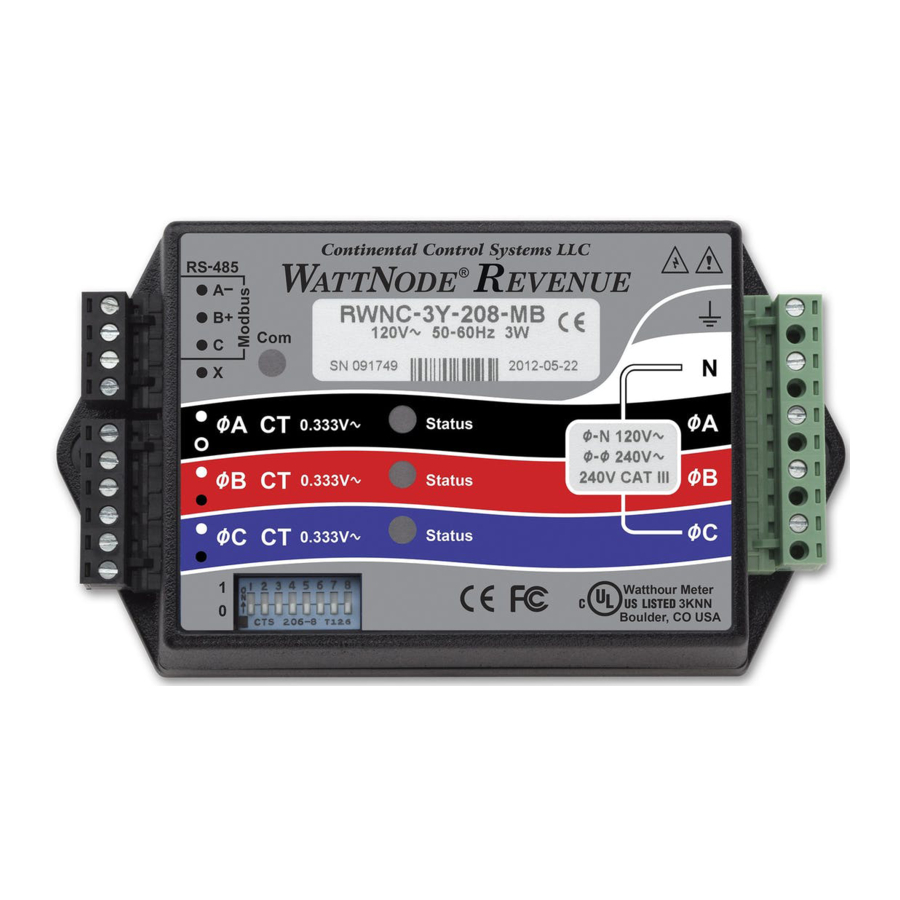
US LISTED 3KNN Figure 1: Front Label Diagram A: WattNode model number. The “WNC” indicates a third generation WattNode meter. The “3” indicates a three-phase model. The “Y” or “D” indicates wye or delta models, although delta models can measure wye circuits (the difference is in the power supply). The “208” (or other value) indicates the nominal line-to-line voltage. - Page 7 CTs that generate a full-scale output of 0.333 Vac (333 millivolts). L: DIP switch. This DIP switch block is used to set the BACnet MAC (network) address and baud rate. See Setting the BACnet Address (p. 20).
-
Page 9: Electrical Service Types
Electrical Service Types Below is a list of service or load types, showing voltages, WattNode types, and which terminals on the WattNode meter operate the power supply. “non-N.A.” refers to non-North American electrical services. Line-to- Meter Electrical Line-to- Meter Line... -
Page 10: Single-Phase Two-Wire With Neutral
Line Current Transformer Neutral Figure 2: Single-Phase Two-Wire Connection Recommended WattNode Models The following table shows the WattNode models that should be used, depending on the line to neutral voltage. Line to Neutral Voltage WattNode Model 120 Vac WNC-3Y-208-BN 230 Vac... -
Page 11: Single-Phase Three-Wire (Mid-Point Neutral)
Figure 3: Single-Phase Three-Wire Connection Recommended WattNode Models The following table shows the WattNode models that can be used. If neutral may or may not be present, you should use the WNC-3D-240-BN (see Single-Phase Two-Wire without Neutral below). If phase B may not be present, you should use the WNC-3Y-208-BN (see Single-Phase Two-Wire with Neutral above). -
Page 12: Single-Phase Two-Wire Without Neutral
Current Transformers Phase B Figure 4: Single-Phase Two-Wire without Neutral Connection Recommended WattNode Model This configuration is normally measured with the following WattNode model. Line-to-Line Voltage WattNode Model 208 - 240 Vac WNC-3D-240-BN If neutral is available, you may also use the WNC-3Y-208-BN model. If you use the WNC-3Y-208-BN, you will need to hook up the meter as shown in section Single-Phase Three- Wire (Mid-Point Neutral) and connect neutral. -
Page 13: Three-Phase Four-Wire Wye
Figure 5: Three-Phase Four-Wire Wye Connection Recommended WattNode Models The following table shows the WattNode models that should be used, depending on the line-to- neutral voltage and line-to-line voltage (also called phase-to-phase voltage). For these models, the meter is powered from the N and ØA terminals. -
Page 14: Three-Phase Three-Wire Delta Without Neutral
CTs are connected to matching phases. For these models, the meter is powered from the ØA and ØB (phase A and phase B) terminals. Note: all delta WattNode models provide a neutral connection N, which allows delta WattNode models to measure both wye and delta configurations. -
Page 15: Mounting
38 mm (1.50 in) High Figure 7: WattNode Meter Dimensions The WattNode meter has two mounting holes spaced 5.375 inches (137 mm) apart (center to center). These mounting holes are normally obscured by the detachable screw terminals. Remove the screw terminals by pulling outward while rocking from end to end. The meter may be used... -
Page 16: Selecting Current Transformers
The effective current rating of the CT is the labeled rating divided by the number of times that the conductor passes through the CT. If you are using the individual phases (ØA, ØB, and ØC) of the WattNode meter to measure different circuits, you can use CTs with different rated current on the different phases. Instead of setting one CtAmps value for all phases, you can use different values for each phase: CtAmpsA, CtAmpsB, and CtAmpsC. -
Page 18: Circuit Protection
● The WattNode meter has an earth connection, which should be connected for maximum accuracy. However, this earth connection is not used for safety (protective) earthing. -
Page 19: Connecting Voltage Terminals
The WattNode meter is powered from the voltage inputs: ØA (phase A) to N (neutral) for wye “-3Y” models, or ØA to ØB for delta “-3D” models. If the meter is not receiving at least 80% of the nomi- nal line voltage, it may stop operating. -
Page 20: Setting The Bacnet Address
Note: the MAC address is not the same as the “Device ID” or “device object identifier”, which may also be used as a BACnet address. In the WattNode, the Device ID defaults to the serial number, but may be changed if necessary over the network. -
Page 21: Wiring
EIA RS-485 networks frequently use bias resistors to hold the bus in a “high” or logic 1 state when no devices are transmitting. In this state, the BACnet “A – “ terminal is more negative than the “B+” terminal. Without bias resistors, the bus can float and noise can appear as bogus data. -
Page 22: Installation Checklist
● Connect the cable shield or BACnet common (if there is no shield) to earth ground at just the BACnet controller end of the cable. Grounding both ends can cause ground loops. Leaving the common “C”... - Page 23 Percent of Full-Scale Power LED Flash Rate Flashes in 10 Seconds 100% 5.0 Hz 2.5 Hz 1.0 Hz 1% (and lower) 0.5 Hz Table 5: LED Flash Rates vs. Power Zero Power For each phase, if line Vac is present, but the measured Green power is below the minimum that the meter will measure;...
- Page 24 ● If there are unused current transformer inputs, install a shorting jumper for each unused CT (a short length of wire connected between the white and black dots marked on the label). ● If there are unused voltage inputs (on the green screw terminal), connect them to neutral (if present) or earth ground (if neutral isn’t available).
-
Page 25: Measurement Troubleshooting
Start by checking the reported voltage (VoltA, VoltB, VoltC) for active (connected) phases. Make sure the voltages match the expected line-to-neutral voltages (or line-to-ground for delta circuits). You should check the actual voltages present at the WattNode meter with a DMM (multimeter) if possible. - Page 26 CT leads are long, interference can occur. Try moving the WattNode meter at least three feet (one meter) away from any VFDs. Use short CT leads if possible. NEVER install the meter downstream of a VFD: the varying line frequency and extreme noise will cause problems! ○...
-
Page 27: Bacnet Communication Diagnostics
The “Com” LED indicates many BACnet communication conditions by lighting green, yellow, or red. BACnet communication errors may also be indicated by returning a BACnet exception response to the controller, by incrementing the Communication Errors (p. 49), or by saving an error code to the ErrorStatus Objects (p. - Page 28 ● An RS-485 adapter on the bus is continuing to drive the transmit lines after sending a packet. If you see this indication, make sure there are not two meters with the same BACnet address. You may want to disconnect all but one meter to see if the problem goes away.
-
Page 29: Operating Instructions
Operating Instructions Quick Start To start communicating with a WattNode BACnet meter using a PC or host device, you’ll need to complete the following steps: ● Set the BACnet address and baud rate using the DIP switches (see Setting the BACnet Address (p. -
Page 30: Bacnet Communication
RS-485 subnet within several seconds of when the devices are connected and powered up. ● Object List: once a new device has been detected, a BACnet host can read the Object_List property of the device object to get a list of all the objects in a WattNode meter. -
Page 31: Floating Point And Integer Values
0.1 kWh. Device Object There is one device object for each WattNode BACnet meter. The device object provides the following properties: ● Object_Identifier (75): Also called the “device identifier” or “device ID”. This is a combina- tion of the Object_Type and Object_Number. -
Page 32: Analog Input Objects - Measurements
● Device_Address_Binding (30): The WattNode does not use Device_Address_Binding and always returns an empty list if this is requested. ● Max_Master (64): This is the highest supported address for master nodes. For the WattNode meter, this is set to 127 and cannot be changed. - Page 33 For all the energy objects (including reactive and apparent energy), there is an additional optional property Integer_Value (1000) that reports the energy value as a 32 bit signed integer value with units of 0.1 kWh (or 0.1 kVARh or 0.1 kVAh). In most cases, you will not need these integer energy values and some systems will not self-discover the custom property Integer_Value.
-
Page 34: Analog Value Objects - Configuration And Diagnostics
† Analog Value Objects - Configuration and Diagnostics The WattNode meter uses analog value objects for configuration and diagnostics. For all the analog value objects the following properties are supported: ● Present_Value (85): This reports or sets the configuration or diagnostic value as a floating point number. - Page 35 Object # Object Name Units Default Description Error Status Objects ErrorStatus1* Newest error or event (0 = no errors) ErrorStatus2* Next oldest error or event ErrorStatus3* Next oldest error or event ErrorStatus4* Next oldest error or event ErrorStatus5* Next oldest error or event ErrorStatus6* Next oldest error or event ErrorStatus7*...
-
Page 36: Binary Value Objects - Configuration
* The Present_Value properties of these objects are preserved across power failures. File Object - Firmware Upgrade The WattNode meter contains a single file object (Object_Number = 0) that is used in conjunc- tion with the AtomicWriteFile service for field firmware upgrades. It is not possible to read the firmware image out of the meter. -
Page 37: Measurement Objects
In the WattNode BACnet meter, most energy objects can be reset to zero by writing “ACTIVE” (1) to the ZeroEnergy object. They can also be set to zero or a preset value by writing the desired value directly to each object. -
Page 38: Per-Phase Energy Objects
The negative energy objects are exactly like the positive energy objects except they accumulate negative energy. The reported energy values will be positive. In other words, if the WattNode measures 1000 kWh of negative energy, EnergyNegSum will report 1000 (not -1000). -
Page 39: Power Objects
Power Objects PowerA, PowerB, PowerC The WattNode meter measures real power (watts) for each phase (PowerA, PowerB, PowerC). The measured power is generally positive, but may also be negative, either because you are generating power (such as with solar panels), or because the meter isn’t connected properly. -
Page 40: Voltage Objects
(see PhaseOffset configuration object). Frequency Freq The WattNode meter measures the AC line frequency in Hertz. All phases must have the same line frequency; otherwise this value will be erratic or incorrect. Current The WattNode BACnet meter estimates the RMS current for each phase. -
Page 41: Demand Objects
Demand is defined as the average power over a specified time interval. Typical demand intervals are 5, 10, 15 (default), 30, 60, etc. up to 720 minutes, but the WattNode meter supports arbitrary demand intervals from 1 to 720 minutes (12 hours). The meter records the peak demand for applications where the measurements may only be accessed weekly or monthly. -
Page 42: Thermistor Temperature Object
Thermistor Temperature Object ThermistorTemp With Option TM1, the WattNode BACnet supports an external thermistor connected between the C and X terminals on the black four-position screw terminal. This external thermistor may then be placed to monitor some external temperature, such as a motor, air temperature, chiller water, etc. -
Page 43: Configuration And Diagnostic Objects
150oC. The WattNode is factory configured for a US Sensor curve J, 10kΩ thermistor. Other 10kΩ therm- istors should work well, but may not be as accurate unless you update the thermistor coefficients as described in Thermistor Configuration below. -
Page 44: Demand Configuration
LEDs. This can be useful if you are trying to identify a particular WattNode meter from a BACnet management tool or software. Set this to “INACTIVE” (0) to turn off the wink pattern. -
Page 45: Thermistor Configuration
Calibration Adjustment GainAdjustA, GainAdjustB, GainAdjustC You may need to adjust the WattNode meter to match the results from a reference meter (such as the utility meter) or to correct for known current transformer errors. The GainAdjust objects effectively adjust the power, energy, and current calibration or registration for each phase. -
Page 46: Zeroing Objects
The following are analog value objects, which report Present_Value as a floating point (32 bit) value. The WattNode only increments UptimeSecs or TotalSecs once per second, so the values should never report a fraction of a second. But the values may be displayed in scientific notation (ie. -
Page 47: Errorstatus Objects
values to increment in jumps larger than one second. For example, between 97 and 194 days, the value will increase by two seconds every two seconds; between 194 and 388 days, the value will increase by four seconds every four seconds, and so on. UptimeSecs This counts the number of seconds the meter has been running since the last power failure or reset. - Page 48 ● 2006: An attempt was made to write a non-writable property ● 2008: An unexpected software reset occurred ● 2009: BACnet receive frame FIFO is full, frame discarded ● 2010: Attempted to write property value below minimum limit ● 2011: Attempted to write property value above maximum limit ●...
-
Page 49: Communication Errors
A framing error indicates a corrupted RS-485 data byte (octet). This may be caused by an incor- rect baud rate, noise, collisions, or an incomplete byte (due to power failure or disconnection). FrameSizeErrorCount The specified application data size is longer than the maximum supported by the WattNode meter (Max_APDU_Length_Accepted). HeaderCRCErrorCount The MS/TP frame header cyclic redundancy check was invalid, indicating a corrupted frame. -
Page 50: Maintenance And Repair
The WattNode meter is not user serviceable. In the event of any failure, the meter must be returned for service (contact CCS for an RMA). In the case of a new installation, follow the diag- nostic and troubleshooting instructions before returning the meter for service, to ensure that the problem is not connection related. -
Page 51: Specifications
* Note: the delta models have an optional neutral connection that may be used for measuring wye circuits. In the absence of neutral, voltages are measured with respect to ground. Delta WattNode models use the phase A and phase B connections for power. Table 8: WattNode Models Model Options Any of these models are available with the following options. -
Page 52: Measurement
Update Rate: 1.0 second. Internally, all measurements are updated at this rate. Start-Up Time: The meter starts making measurements approximately 300 milliseconds after AC power is applied, and enables the BACnet MS/TP interface one second later. Default Current Transformer Phase Angle Correction: 0.0 degrees The CT phase angle correc- tion can be changed using the PhaseAdjustA, PhaseAdjustB, PhaseAdjustC objects. -
Page 53: Bacnet Protocol Implementation Conformance Statement (Pics)
BACnet Standardized Device Profile (Annex L) BACnet Application Specific Controller (B-ASC) BACnet Smart Sensor (B-SS) The WattNode BACnet is primarily a smart sensor (B-SS), but also includes the characteristics of an application specific controller (B-ASC). List all BACnet Interoperability Building Blocks (BIBBs) Supported (Annex K) -
Page 54: Electrical
The power supply draws most of the total power consumed, while the measurement circuitry draws 1-10% of the total (6-96 mil- liwatts per phase, depending on the model). Due to the design of the power supply, WattNode meters draw slightly more power at 50 Hz. -
Page 55: Certifications
WNC-3Y-480-BN 480 Vac WNC-3D-480-BN WNC-3Y-600-BN 600 Vac Table 10: WattNode CAT III Ratings Current Transformer Inputs: Nominal Input Voltage (At CT Rated Current): 0.33333 Vac RMS Absolute Maximum Input Voltage: 5.0 Vac RMS Input Impedance at 50/60 Hz: 23 kΩ Certifications Safety: UL 61010-1 (E312220);... -
Page 56: Thermistor Input Specifications
Thermistor Configuration Objects: Added ThermistorCoeffA, ThermistorCoeffB, and ThermistorCoeffC analog value objects the thermistor Steinhart-Hart coefficients. BTL: The firmware for the WattNode BACnet with option TM1 (thermistor input) is not BTL (BACnet Testing Laboratories) certified. However, it is based on a firmware version that is BTL certified and has been tested by CCS with the VTS test suite. -
Page 57: Current Transformers
None of these CTs measure DC current and the accuracy can be degraded in the presence of DC currents, as from half-wave rectified loads. WattNode meters should only be used with UL Recognized or UL Listed current transformers, which are available from Continental Control Systems. Using non-approved CTs will invalidate the meter UL listing.
Need help?
Do you have a question about the BACnet and is the answer not in the manual?
Questions and answers