Advertisement
Quick Links
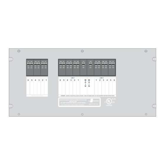
50 AMP Smart Energy Management System Model 800
6
5
INVERTER LOADS SUBPANEL
The 50 AMP SMART EMS - Model 800 i
from the 120/240 volt power source is fed into the box. The potential of lethal electrical shock is present in this
box. Inadvertent shorts at this box could result in damage and/or injury. All servicing of this box should be done
ONLY by a qualified Service Technician.
Diagnostic tools required: Low current Test Light, Accurate Voltmeter (digital read-out preferred),
Intellitec
www.intellitec.com
SERVICE MANUAL
50 Amp EMS Display Panel
P/N 00-00903-050 (Ivory)
P/N 00-00903-150 (Black)
4
3
2
1
6
5
4
DANGER:
HAZARD OF ELECTRICAL SHOCK OR BURN. TURN OFF POWER SUPPLY ON THIS EQUIPMENT BEFORE WORKING INSIDE.
SMARTENERGYMANAGEMENTSYSTEM
50 AMP SERVICE MAIN & SUB PANEL
ENCLOSED ENERGY MANAGEMENT EQUIPMENT
50 AMP EMS MODEL 800 DISTRIBUTION PANEL
s a centralized power switching, fusing and distribution center. Power
Clamp-on AC ammeter.
50 AMP
SMART EMS
LINE 1
LINE 2
3
2
1
M
M
1
2
A
A
I
I
N
N
by
Intellitec
MODEL800
MADE IN THE U.S.A.
P/N 00-00894-300
CAUTION
1
TM
3
4
5
6
4L54
C
US
R
LISTED
131 Eisenhower Lane North
630.268.0010 / 1.800.251.2408
P/N 53-00894-100 Rev. E 030807
Lombard, IL 60148
Advertisement

Related Manuals for Intellitec 800

Summary of Contents for Intellitec 800
- Page 1 P/N 00-00894-300 CAUTION The 50 AMP SMART EMS - Model 800 i s a centralized power switching, fusing and distribution center. Power from the 120/240 volt power source is fed into the box. The potential of lethal electrical shock is present in this box.
- Page 2 12 circuits, including Energy Management of up to six selected branch circuits. A sub- panel is available on the Model 800 for up to 6 sub-breakers for inverter connected loads. If 120 VAC - 30/20 Amp source is available, the control helps to limit the total current draw of all the appliances in the RV at or below 30/20 Amps provided by the main power feed.
- Page 3 50 AMP Smart Energy Management System Model 800 CONTROLLED LOADS The system offers control of up to six powered loads; each one connected to one of the relay circuits of the 50 AMP Smart system. Four of these relays, relays 1, 2, 3, and 4, are 30 Amp relays with normally-open contacts used to interrupt the 120 volt power to the loads.
-
Page 4: Display Panel
50 AMP Smart Energy Management System Model 800 50 AMP SMART EMS DISPLAY PANEL The Display Panel can be mounted remotely and connects to the main unit with a light gauge, three-wire cable. Six Power Status LED's indicate power is applied to those loads. These LED's are ON when the power is applied. If 120 VAC service is available, the Load Meter has a two-digit display to indicate the amount of current actually being drawn by all the appliances in the coach. - Page 5 50 AMP Smart Energy Management System Model 800 INSTALLATION THE CONTROL MODULE The first step when installing an EMS, is to determine which loads will be controlled and in what order they will be shed. A typical scheme would be to control the two air conditioners, the water heater and the washer/dryer. With these loads, the first...
- Page 6 The 00-00903-XYZ displays have had a recent software update to allow the decoding of the relay 1 led indicator. Displays date coded after Feb. 5, 2007 will have this software update. Intellitec Julian Date code of 030607 or newer. Julian date code is the following: first three digits are number of days into the year and the last digits is the year.
-
Page 7: Distribution Panel
50 AMP Smart Energy Management System Model 800 DISTRIBUTION PANEL The EMS Distribution Panel should be installed in a convenient location where it can get air circulation to keep it from over heating. There should be a minimum of 7" of depth behind the mounting surface to provide enough room for the box and wiring. - Page 8 NOTE To insure proper operation of the source sensing circuitry on the 50 AMP EMS Model 800, jumper wires must always be connected from a Line 1 breaker to J6 terminal 3, and from a Line 2 breaker to J6 terminal 1.
- Page 9 50 AMP Smart Energy Management System Model 800 DISTRIBUTION PANEL (continued) The low voltage controlled load connections are made through J4 (6 pin Mate-N-Lok connector on the low voltage side of the control module). Connections are as follows: J4 Pin...
-
Page 10: Performance Test
50 AMP Smart Energy Management System Model 800 DISPLAY PANEL Select a convenient location for the panel, where it can be easily viewed by the owner. Cut a hole for the panel as shown: The Display Panel is equipped with a six inch long pigtail with a 3-pin Mate-N-Lock female connector. An extension harness, up to 100 feet long, can be attached between the Display Panel and the EMS Control Module, with a 3-pin male Mate-N-Lock plug at the Display Panel end and a 4-pin, male, Mate-N-Lock plug at the Control Module end. -
Page 11: System Test
50 AMP Smart Energy Management System Model 800 SYSTEM TEST All the 120 volt loads should be turned off, or disconnected. Both 120 volt AC and 12 volt DC power should now be applied to the system. When this is done, the relays should be heard pulling in. On the Display Panel, the numeric display should read "0", the six Power Status LED's should come ON, and the "30 Amp"... - Page 12 50 AMP Smart Energy Management System Model 800 EMS CONTROL MODULE PLUGS, PINS, AND FUNCTIONS (continued) J5 = 4 pin Molex KK .156 - Display Panel Connector Mating Housing Molex 09-50-3041 Function Power Data IN GROUND RV Master Com OUT...
- Page 13 50 AMP Smart Energy Management System Model 800 TROUBLE SHOOTING If the following problems occur, proceed with analysis in the order in which these steps are listed: No 120 VOLT appliances working. A. Check incoming power source. 1. Make sure the shore power cord is plugged into the outlet.
- Page 14 50 AMP Smart Energy Management System Model 800 TROUBLE SHOOTING (continued) VI. Shedding order incorrect. A. Check jumper setting (Figure on page 5 and Tables on page 6.) B. Check relay wiring per Table on page 6. VII. Remote Display out, or strange characters are displayed.
- Page 15 50 AMP Smart Energy Management System Model 800 131 Eisenhower Lane North Intellitec Lombard, IL 60148 630.268.0010 / 1.800.251.2408 P/N 53-00894-100 Rev. E 030807 www.intellitec.com...
- Page 16 50 AMP Smart Energy Management System Model 800 131 Eisenhower Lane North Intellitec Lombard, IL 60148 630.268.0010 / 1.800.251.2408 P/N 53-00894-100 Rev. E 030807 www.intellitec.com...
Need help?
Do you have a question about the 800 and is the answer not in the manual?
Questions and answers