
Subscribe to Our Youtube Channel
Related Manuals for esky Eyas


Summary of Contents for esky Eyas
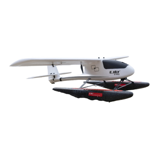
- Page 1 ESKY Float Installation Instructions 浮筒安装说明书 * EYAS Fuselage is NOT included in this package * * 此包装不包含 EYAS 机身 *...
- Page 2 Languages 语言 English ................................1 - 1 7 中文 .................................. 1 8 - 3 4...
-
Page 3: Table Of Contents
RC aircraft is controlled by radio signals. It may be interfered by other radio signals during operation. These interference may cause the aircraft lose control. 1. Improper operation to ESKY EYAS may lead to damage or loss. lt is prohibited for children under 14 years to operate this product. -
Page 4: Exploded View (New Fuselage)
Exploded View (New Fuselage) Fuselage (NOT Included) Screw x1 M2x8mm Screw x1 Front Strut Mount M1.7x6mm Screw x2 Water Rudder M2.5x15mm Screw x4 M3x45mm Rear Strut x2 Carbon Fiber Bar (Cross Brace) x2 Front Strut Screw x2 M3x10mm Float (R) Float (L) -
Page 5: New And Old Fuselage Comparison
New and Old Fuselage Comparison The difference between New and Old Fuselage is on the rear New Fuselage (Plastic Part Included) Old Fuselage (Plastic Part NOT Included) Box Contents M 2 . 5 x 1 5 m m M 2 x 8 m m M 2 x 3 m m M 1 . -
Page 6: Assemble The Float (New Fuselage)
Assemble the Float (New Fuselage) Water Rudder Installation 1. Tools Required: 1.5mm Hex Screwdriver 2. Parts Required: Water Rudder, Water Rudder Rod, Screw M2x8mm, Screw M1.7x6mm M2x8mm M1.7x6mm 3. Installation Diagram 4. Installation Diagram Fuselage *NOT Included* Screw M1.7x6mm Screw M2x8mm Water Rudder... - Page 7 Assemble the Float (New Fuselage) Front Strut Mount Installation 1. Tools Required: 2.0mm Hex Screwdriver 2. Parts Required: Front Strut Mount, Screw M2.5x15mm x2 M2.5x15mm Front 3. Installation Diagram Front Screw M2.5x15mm...
- Page 8 Assemble the Float (New Fuselage) Front Strut and Rear Strut Installation 1. Tools Required: 2.0mm Hex Screwdriver 2. Parts Required: Front Strut, Rear Strut, Screw M3x10mm x2 M3x10mm 3. Installation Diagram Fuselage Rear Strut *NOT Included* Screw M3x10mm Front Strut Front Strut Mount Rear Strut...
-
Page 9: Assemble The Float (Old Fuselage)
Assemble the Float (New Fuselage) Float Installation 1. Tools Required: 2.0mm Hex Screwdriver 2. Parts Required: Float (L), Float (R), Carbon Fiber Bar (Cross Brace) x2, Screw M3x45mm x4 M3x45mm 3. Installation Diagram Rear Strut Screw M3x45mm Fuselage *NOT Included* Float (L) Front Strut Float (R) - Page 10 Assemble the Float (Old Fuselage) Water Rudder Installation 1. Tools Required: 1.5mm Hex Screwdriver, Utility Knife, 502 Super Glue 2. Parts Required: Water Rudder, L Shape Rod, Metal Grip, Incision Stickers, Screw M1.7x6mm, Screw M2x3mm M 1 . 7 x 6 m m M 2 .
- Page 11 Assemble the Float (Old Fuselage) L Shape Rod and Water Rudder Installation Insert the L Shape Rod into 2mm hole L Shape Rod 2mm Hole The L Shape Rod passes through into the fuselage as shown below L Shape Rod passes through from here...
- Page 12 Assemble the Float (Old Fuselage) L Shape Rod and Water Rudder Installation Cut the slot but do not cut completely through the rudder then push the rod into the slot Install the Water Rudder to the fuselage using the M2x3mm screw Ensure the hole of the grip and the flat side of the rod should align as shown below Flat side in the rod Metal Grip Hole...
- Page 13 Assemble the Float (Old Fuselage) L Shape Rod and Water Rudder Installation Both Rudder should align Both Rudder should align Apply 502 Super Gule to the slot which you cut to install the L Shape Rod Do not apply 502 Super Gule into the 2mm hole Only apply 502 Super Gule to the slot...
- Page 14 Assemble the Float (Old Fuselage) L Shape Rod and Water Rudder Installation Cover the slot using the Incision Stickers when the 502 Super Glue is dry Incision Stickers Position...
- Page 15 Assemble the Float (Old Fuselage) Front Strut Mount Installation 1. Tools Required: 502 Super Glue 2. Parts Required: Front Strut Mount Front 3. Installation Diagram Double Sided Tape *The double sided tape had been already installed on the front strut mount. Tear one side for installation*...
- Page 16 Assemble the Float (Old Fuselage) Front Strut Mount Installation Attach the front strut mount to the existing nose gear mount Front Front Strut Mount Fix the front strut mount as below setting out Front 7 m m Left Right 7 m m...
- Page 17 Assemble the Float (Old Fuselage) Front Strut Mount Installation Apply 502 Super Glue to each side of gap between the existing nose gear mount and front strut mount as “A” shown below Hold and press the front strut mount around 15-20 seconds until the mount is completely fixed Hold and press the front strut mount around 15-20 seconds...
- Page 18 Assemble the Float (Old Fuselage) Front Strut and Rear Strut Installation 1. Tools Required: 2.0mm Hex Screwdriver 2. Parts Required: Front Strut, Rear Strut, Screw M3x10mm x2 M3x10mm 3. Installation Diagram Fuselage Rear Strut *NOT Included* Screw M3x10mm Front Strut Front Strut Mount Rear Strut...
- Page 19 Assemble the Float (Old Fuselage) Float Installation 1. Tools Required: 2.0mm Hex Screwdriver 2. Parts Required: Float (L), Float (R), Carbon Fiber Bar (Cross Brace) x2, Screw M3x45mm x4 M3x45mm 3. Installation Diagram Rear Strut Screw M3x45mm Fuselage *NOT Included* Float (L) Front Strut Float (R)
- Page 20 目录 安 全 注 意 事 项 和 警 告 ..................安...
- Page 21 安装分解图(基于新版机身) 机 身 ( 不 包 含 ) 螺 丝 M 2 x 8 m m 螺 丝 前 支 架 固 定 座 M 1 . 7 x 6 m m 螺 丝 水 舵 M 2 . 5 x 1 5 m m 螺...
- Page 22 新旧版本机身的区别 新 旧 版 本 机 种 的 区 别 体 现 在 尾 部 。 新 版 本 机 身 ( 有 塑 胶 件 ) 旧 版 本 机 身 ( 无 塑 胶 件 ) 浮筒套件包含物料 M 2 . 5 x 1 5 m m M 2 x 8 m m M 2 x 3 m m M 1 .
- Page 23 新版本机身浮筒套件安装说明 水 舵 组 件 的 安 装 1 . 自 备 工 具 : 1 . 5 m m 六 角 螺 丝 刀 2 . 安 装 所 需 物 件 : 水 舵 , 水 舵 杆 , M 2 x 8 m m 螺 丝 x 1 , M 1 . 7 x 6 m m 螺 丝 x 1 M 2 x 8 m m M 1 .
- Page 24 新版本机身浮筒套件安装说明 前 支 架 固 定 座 的 安 装 1 . 自 备 工 具 : 2 . 0 m m 六 角 螺 丝 刀 2 . 安 装 所 需 物 件 : 前 支 架 固 定 座 , M 2 . 5 x 1 5 m m 螺 丝 x 2 M 2 .
- Page 25 新版本机身浮筒套件安装说明 前 支 架 和 主 支 架 的 安 装 1 . 自 备 工 具 : 2 . 0 m m 六 角 螺 丝 刀 2 . 安 装 所 需 物 件 : 前 支 架 , 主 支 架 , M 3 x 1 0 m m 螺 丝 x 2 M 3 x 1 0 m m 3 .
- Page 26 新版本机身浮筒套件安装说明 浮 筒 的 安 装 1 . 自 备 工 具 : 2 . 0 m m 六 角 螺 丝 刀 2 . 安 装 所 需 物 件 : 浮 筒 ( L ) , 浮 筒 ( R ) , 支 架 板 x 2 , M 3 x 4 5 m m 螺 丝 x 4 M 3 x 4 5 m m 3 .
- Page 27 旧版本机身浮筒套件安装说明 水 舵 组 件 的 安 装 1 . 自 备 工 具 : 1 . 5 m m 六 角 螺 丝 刀 , 美 工 刀 , 5 0 2 胶 水 2 . 安 装 所 需 物 件 : 水 舵 , L 形 钢 丝 , 金 属 夹 头 , 覆 盖 贴 纸 , M 1 . 7 x 6 m m 螺 丝 , M 2 x 3 m m 螺 丝 M 1 .
- Page 28 旧版本机身浮筒套件安装说明 金 属 夹 头 与 水 舵 的 组 装 下 图 所 示 , 将 L 形 钢 丝 垂 直 插 入 机 身 上 的 2 m m 圆 孔 钢 丝 L 形 2 m m 的 圆 孔 下...
- Page 29 旧版本机身浮筒套件安装说明 金 属 夹 头 与 水 舵 的 组 装 下 图 所 示 , 使 用 美 工 刀 在 图 示 位 置 划 开 一 道 口 子 , 不 用 切 穿 发 泡 机 体 , 能 将 钢 丝 的 尾 端 压 入 即 可 使...
- Page 30 旧版本机身浮筒套件安装说明 金 属 夹 头 与 水 舵 的 组 装 下 图 所 示 , 从 机 身 尾 部 往 前 看 , 将 水 舵 与 方 向 舵 调 整 到 处 于 同 一 直 线 上 处...
- Page 31 旧版本机身浮筒套件安装说明 金 属 夹 头 与 水 舵 的 组 装 下 图 所 示 , 使 用 随 机 附 带 的 覆 盖 贴 纸 覆 盖 切 口 位 置 覆 盖 贴 纸 位 置...
- Page 32 旧版本机身浮筒套件安装说明 前 支 架 固 定 座 的 安 装 1 . 自 备 工 具 : 5 0 2 胶 水 2 . 安 装 所 需 物 件 : 前 支 架 固 定 座 前 部 3 . 安 装 步 骤 图 解 双...
- Page 33 旧版本机身浮筒套件安装说明 前 支 架 固 定 座 的 安 装 如 下 图 所 示 将 前 支 架 固 定 座 贴 合 在 前 机 身 底 部 塑 胶 件 上 前 部 前 支 架 固 定 座 如...
- Page 34 旧版本机身浮筒套件安装说明 前 支 架 固 定 座 的 安 装 在 前 支 架 固 定 座 与 塑 胶 底 座 接 触 的 4 个 边 缘 位 置 ( 下 图 中 的 A ) 上 滴 入 适 量 的 5 0 2 胶 水 将...
- Page 35 旧版本机身浮筒套件安装说明 前 支 架 和 主 支 架 的 安 装 1 . 自 备 工 具 : 2 . 0 m m 六 角 螺 丝 刀 2 . 安 装 所 需 物 件 : 前 支 架 , 主 支 架 , M 3 x 1 0 m m 螺 丝 x 2 M 3 x 1 0 m m 3 .
- Page 36 旧版本机身浮筒套件安装说明 浮 筒 的 安 装 1 . 自 备 工 具 : 2 . 0 m m 六 角 螺 丝 刀 2 . 安 装 所 需 物 件 : 浮 筒 ( L ) , 浮 筒 ( R ) , 支 架 板 x 2 , M 3 x 4 5 m m 螺 丝 x 4 M 3 x 4 5 m m 3 .
Need help?
Do you have a question about the Eyas and is the answer not in the manual?
Questions and answers