
Subscribe to Our Youtube Channel
Related Manuals for Barrus X05


Summary of Contents for Barrus X05
- Page 1 ORIGINAL INSTRUCTION ELECTRIC OUTBOARD MOTOR OPERATORS MANUAL For the following models: RDG603B2 – Issue 1...
- Page 2 SAFETY Barrus is concerned for your safety. We use safety statements throughout the manual to call your attention to the potential hazards associated with the operation of your electric propulsion outboard. Follow the precautions listed throughout the manual before operation, during operation and during servicing/maintenance procedures for your safety, the safety of others and to protect the performance of your motor.
- Page 3 Engine Details Engine Model Number: Engine Serial Number: Please enter your engine model number and serial number in the space provided above. Please quote the engine identification number during any enquiry or when ordering spare parts. Information about the engine serial number and its location on the engine can be found in SECTION 2 of the manual.
- Page 4 Outboard specifications, Benefits and Optional extras Specifications: • 48 Volt electric outboard • CE Marked • UKCA Marked • Water cooled permanent magnet, brushless electric motor • Variable speed • Adjustable leg length from short to long shaft • Outboard tilt lock •...
- Page 5 IF A TRANSFER OF TITLE OCCURS, IT MUST ALWAYS BE HANDED OVER TO THE NEW OWNER. Thank you for purchasing this electric outboard motor from Barrus. This manual has been compiled to help you to operate your outboard and its associated parts with safety and pleasure.
- Page 6 Barrus. CONDITIONS THAT MUST BE MET IN ORDER TO OBTAIN WARRANTY COVERAGE Warranty coverage is only available from Barrus or an authorised dealer in the country in which the sale occurred. Routine maintenance outlined in the Owner’s Manual must be performed using genuine parts in order to maintain warranty coverage.
- Page 7 Damage due to rust or corrosion, submersion, or unreasonable exposure to the environment, such as exposure to high humidity, rain fall, or seawater, or conditions resulting in the freezing of cooling water are also not covered. RDG603B2 – Issue 1 Page 7 of 88...
-
Page 8: Table Of Contents
Index Page SECTION 1 – Safety Precautions..................11 1. General ......................... 11 2. Lifting ..........................11 3. Rotating Parts ....................... 11 4. Propeller ........................12 5. Electrics ........................12 6. Batteries ........................12 7. Safety Lanyard ......................13 8. Motor Overload ......................14 9. - Page 9 7. Application Downloads and Information ................ 39 SECTION 5 – Maintenance ....................42 1. General ......................... 42 2. Installing propeller (X05) ....................43 3. Installing Propeller (X10) ....................44 4. Controller Alignment ...................... 47 SECTION 6 – Transportation and Storage ............... 48 1.
- Page 10 4. STAZO Outboard Lock ....................57 5. Talamex Outboard Motor Lock ..................58 SECTION 12 – Afterlife Recycling ..................59 SECTION 13 – Declarations ....................60 1. Declaration of Conformity for Recreational Craft Propulsion Engine with the requirements of Directive 2012/53/EU................60 2.
-
Page 11: Section 1 - Safety Precautions
SECTION 1 – Safety Precautions 1. General NOTICE: NEVER PERMIT ANYONE TO OPERATE THE OUTBOARD WITHOUT PROPER TRAINING. Ensure that the engine battery isolator switch is in the off position before connecting the battery or carrying out any maintenance/ repairs. Also, when the outboard is not in use. 2. -
Page 12: Propeller
The outboard and its accessories are not intended to be put into operation until they are integrated into the boat as a whole. The top cowl must always be fitted whilst the motor is running. 4. Propeller CAUTION • The propeller has sharp edges which can cause injury even when it is stationary. If there is someone in the water near the motor, it must be switched off. -
Page 13: Safety Lanyard
WARNING: BURN HAZARD! BATTERIES CONTAIN SULPHURIC ACID. NEVER ALLOW BATTERY FLUID TO COME IN CONTACT WITH SKIN, EYES OR CLOTHING. SEVERE BURNS COULD RESULT. MAKE SURE THE CORRECT PERSONAL PROTECTION EQUIPMENT IS WORN. • Batteries can produce explosive gases; keep sparks and flames away from the battery. NO SMOKING •... -
Page 14: Motor Overload
Figure 1: Safety Lanyard The outboard will not operate if the safety lanyard is not in place. Ensure there is a spare one on the boat and passengers know where it is. 8. Motor Overload • If the motor is excessively overloaded (by either extended running at high speed or using a propeller which is too big for the application) the motor will derate. -
Page 15: Terminal Crimping
12. Terminal Crimping Ensure that a professional type crimping tool is used for crimping all heavy-duty cable connections. Failure to do so can result in poor performance, system failure, terminal overheating or in some cases melting of plastic terminal plugs or even fires. 13. -
Page 16: Section 2 - Component Identification
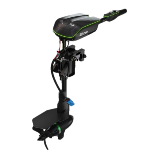
SECTION 2 – Component Identification 1. Tiller Control Model Description* Outboard Cowl Tiller Control Transom Mounting Bracket Anti-Cavitation Plate Motor Propeller Figure 2: Tiller Controlled Outboard 2. Tiller Control Description* Speed Control Twist Grip Direction Display Safety Lanyard Mode Switch On/Off Power Button Neutral Position Indicator Figure 3: Tiller Control... -
Page 17: Remote Control Model (Option)
3. Remote Control Model (Option) Description* Steering Wheel Speed and Direction Control Lever Steering Cable Electric Outboard Figure 4: Remote Controlled Outboard Note: A number of optional extras may be fitted to the outboards, that are not shown here. 4. Speed and Direction Control Lever (Option) Description* Safety Lock Control Grip... -
Page 18: Section 3 - Installation
SECTION 3 – Installation NOTICE: REFER TO THE BARRUS MANUAL PRIOR TO INSTALLING THE MOTOR. 1. Unpacking the Outboard Motor • The outboard motor will arrive in a wooden box. Section 8.3 details shipping weight and packaging dimensions. Use suitable personal protective equipment for unboxing. -
Page 19: Adjusting The Outboard Motor Transom Height
Note: There is a right-handed speed and direction control lever available at an additional cost (Part No.: GM-TRC-010R) Note: Assembly instructions can be found in Section 5 - Maintenance. 2. Adjusting the Outboard Motor Transom Height Note: The outboard has an adjustable transom height system, there are a number of positions to choose from between short and long shaft. -
Page 20: Mounting Of The Outboard Motor
3. Mounting of the Outboard Motor • The outboard needs to be mounted so that the boat is balanced. For single-engine boats mount the outboard motor on the centre line (keel line) of the boat. Centre Line Figure 10: Centre Line (Keel Line) •... - Page 21 It is important that the outboard is installed at the correct height. If it is mounted too high, air will enter the propeller area and cause cavitation. This will cause loss of drive, noisy operation and loss of maximum potential speed. If it is mounted too low, it will cause excessive drag in the water, using more power.
-
Page 22: Adjusting The Outboard Steering Lock
4. Adjusting the Outboard Steering Lock • The outboard steering sensitivity can be adjusted by tightening or loosening the steering lock bolt. • The outboard will arrive with the bolt fully tightened, to maintain stability during transport and initial assembly. Steering Lock Bolt Figure 13: Steering Lock Bolt... -
Page 23: Battery Selection
Only one 48V Barrus battery module is required to run the X-series outboards. Additional battery modules can be added to increase the range. Battery modules can be easily connected in parallel to form a larger capacity battery bank. - Page 24 display: Voltage Figure 15: Voltage Display Current Draw Figure 16: Amps Display Amp Hours Figure 17: Amp Hours Display Battery Percentage Figure 18: Battery Percentage Display RDG603B2 – Issue 1 Page 24 of 88...
- Page 25 • The battery percentage display acts in a similar way to a fuel gauge, with 100% being full (fully charged) and 0% being empty (discharged). Single 48V 30Ah (Amp Hour) and Single 48V 50Ah Battery Specification 48V/ 30Ah (EB4830) 48V/ 50Ah (EB4850) Weight 16kg 27kg...
-
Page 26: Battery Features (Eb-4830 / Eb-4850)
Anderson Type Cable Connection Battery Isolation Switch Figure 19: Battery Connections • The outboard motor voltage is 48v (one EB-4830 or one EB-4850 Lithium-Ion battery). • The table below shows the minimum battery and equipment specification required for the different outboard motor models. •... - Page 27 disappear. If the battery is reconnected to the charger, plugged into the mains supply and switched on, it will re-boot the battery and turn it back on again. Multi-Plug Connector • A full-size multi plug with a short cable is supplied to allow for quick connect or disconnect.
- Page 28 • Alternatively, the outboard motor can be powered by suitable deep cycle traction batteries, sourced by the customer. • The table below shows the minimum battery and equipment specification required for the different outboard motor models. Minimum Battery Minimum Minimum Battery Model Isolation Switch Cable Size...
-
Page 29: Lithium-Ion Polymer (Lifepo4) Batteries Precautions (Eb-4830 / Eb-4850)
been discharged. Battery Supply Battery Charging Time (Hours) 4 x 12V 85Ah Deep Cycle AGM Traction Battery 4 (Approx.) 4 x 12V 105Ah Deep Cycle AGM Traction Battery 6 (Approx.) 9. Lithium-Ion Polymer (LiFePO4) Batteries Precautions (EB-4830 / EB-4850) • Do not store or use the battery at high temperature, this prevents overheating. •... -
Page 30: Anderson Type Connectors
• The cables for the batteries and the electric outboard are connected using Anderson type connectors (Figure 22). Figure 22: Anderson Type Connector • The table below shows the specification of the Anderson type connector X05 / X10 UL Current Rating (Amperes) UL Voltage Ratings (Volts) AVG Contact Resistance (micro-ohms) -
Page 31: Battery Storage
• The system also has a fuse (Circled on Figure 23) mounted on the main power inlet cable on the outboard. Figure 23: Fuse Position on a X05 Outboard 15. Battery Storage All batteries should be stored in a warm/ dry environment, fully charged and isolated from the electric outboard. - Page 32 Figure 24: Control Lever connected to Outboard Motor RDG603B2 – Issue 1 Page 32 of 88...
-
Page 33: Section 4 - Operation
SECTION 4 – Operation NOTICE: REFER TO THE BARRUS MANUAL PRIOR TO OPERATING THE MOTOR. 1. General • Familiarize yourself with the electric outboard controls. For example, you must be able to stop the electric outboard quickly if required, or in an emergency. -
Page 34: Starting Procedure (Outboard Motor With Tiller Control)
2. Starting Procedure (Outboard Motor with tiller control) • Attach the magnetic safety lanyard to the tiller arm of the outboard (Figure 25). Figure 25: Safety Lanyard attached to the stop switch • Attach the other end of the safety lanyard to the operator’s life jacket or leg. The outboard will not operate if the safety lanyard is not attached. -
Page 35: Starting Procedure (Outboard Motor With Speed And Direction Control Lever)
3. Starting Procedure (Outboard motor with speed and direction control lever) • Ensure that the lever is in the neutral position. • Attach the safety lanyard to the control lever connected to the outboard (Figure 26). Locking Safety Button Safety Lanyard Power (on/ off) Switch... -
Page 36: Stopping Procedure (Outboard Motor With Tiller Control)
Figure 27: Speed and Direction Control Lever in forward position 4. Stopping Procedure (Outboard Motor with tiller control) • Put the speed of the motor to the neutral position using the speed control twist grip. This will stop the propeller. •... -
Page 37: Tilting The Electric Outboard
6. Tilting the Electric Outboard To put the electric outboard in the raised position: Ensure the motor is stopped and the battery disconnected. • Open the quick release handle. Figure 28: Tilt Lock Lever • Lift and tilt the electric outboard up. Lift and tilt the outboard until the lift latch engages and this will hold the leg in the raised position. - Page 38 To put the electric outboard in the down position: • Tilt the leg slightly up and move the release lever out. Slowly, tilt the outboard down and release the lever. Figure 30: Outboard release lever (being pulled out to lower the motor) •...
-
Page 39: Application Downloads And Information
• The speed logged can be shown in either km/h or mph. • This is particularly useful if not using the Barrus (EB-4830 / EB-4850) LiFePO4 batteries as alternative batteries are unlikely to have the visual display gauge on top (See figures 15,16,17 and 18). - Page 40 • After you have connected the Bluetooth adaptor, replace the cowl. Figures 33 & 34: App Manual Note: Often the motor will appear as “LDMC” or similar on the in-app Bluetooth menu. Note: The app may appear in a different layout on the iPhone version. •...
- Page 41 • The app has the ability to set the 3 modes to different percentages of maximum throttle. The default for each of the three modes is: Economic 25%, Normal 60% and Sport 100%. These can be altered to the desired percentages at your own discretion. To do so, open the settings tab as explained in part 4 above.
-
Page 42: Section 5 - Maintenance
SECTION 5 – Maintenance NOTICE: REFER TO THE BARRUS MANUAL PRIOR TO CARRYING OUT ANY MAINTENANCE WORK. WARNING: PRIOR TO CARRYING OUT ANY SERVICE OR MAINTENANCE WORK MAKE SURE THE RELEVANT PERSONAL PROTECTION EQUIPMENT IS WORN. 1. General • The person who is to carry out the maintenance of the outboard motor needs to have the relevant mechanical and electrical competence to do so. -
Page 43: Installing Propeller (X05)
2. Installing propeller (X05) • Insert cylindrical pin into the upper hole of the motor shaft. Figure 36: Cylindrical Pin (X05) • Fit propeller and nylon washer Figure 37: Fitment of the Propeller (X05) RDG603B2 – Issue 1 Page 43 of 88... -
Page 44: Installing Propeller (X10)
• Fit stainless steel washer, slotted nut and split pin. Figure 38: Fitment of Propeller Nut (X05) 3. Installing Propeller (X10) • Fit ceramic bearing to the motor shaft. Figure 39: Propeller Bearing Fitting RDG603B2 – Issue 1 Page 44 of 88... - Page 45 • Fit washers and bearing in the order shown in Figure 40. Figure 40: Ceramic Bearing Fitting • Insert the cylindrical pin through the upper hole of the motor shaft. Figure 41: Cylindrical Pin (X10) RDG603B2 – Issue 1 Page 45 of 88...
- Page 46 • Fit propeller and nylon washer. Figure 42: Fitment of the Propeller (X10) • Fit stainless steel washer, slotted nut and split pin. Figure 43: Fitment of Propeller Nut (X10) RDG603B2 – Issue 1 Page 46 of 88...
-
Page 47: Controller Alignment
4. Controller Alignment • Ensure the controller unit base is parallel to the motor. Figure 44: Alignment of the Controller Unit RDG603B2 – Issue 1 Page 47 of 88... -
Page 48: Section 6 - Transportation And Storage
SECTION 6 – Transportation and Storage 1. Transporting • When the outboard motor is removed from the boat, lay it down horizontally or put the outboard motor back in the original box. 2. Storage • Store the outboard motor in a well ventilated, dry storage area. •... -
Page 49: Section 7 - Wiring Diagrams
SECTION 7 – Wiring Diagrams 1. Wiring Diagram for Electric Propulsion Outboard Figure 45: Outboard Wiring Diagram (X05/ X10) RDG603B2 – Issue 1 Page 49 of 88... -
Page 50: Section 8 - Technical Data
SECTION 8 – Technical Data 1. Outboard Data Model Output (kW) Approximate Equivalent Petrol Engine Power (hp) Rated Voltage (Vdc) Input Current (A) Max Propeller Speed (r/min) 2000 2600 Propeller (in) 10 x 7 10 x 7 Thrust (Ib) Trim and Tilt System Mechanical Mechanical Control System... -
Page 51: Outboard Dimensions
4. Outboard Dimensions Figure 46: X05 Outboard Motor Dimensions RDG603B2 – Issue 1 Page 51 of 88... - Page 52 Figure 47: X10 Outboard Motor Dimensions RDG603B2 – Issue 1 Page 52 of 88...
-
Page 53: Section 9 - System Protection Characteristics
SECTION 9 – System Protection Characteristics In the event of the operating system receiving a fault code, the controller will sound out one of the following error codes via a number of beeps. System Protection Feature Description No. of Beeps Battery voltage is higher than default Over–voltage protection value. -
Page 54: Section 10 - Spare Parts
SECTION 10 – Spare Parts Item Picture Rotor Assembly GM18.001.037 GM18.001.038 Motor Controller GM-VEC72220 GM-VEC72300 Controller Wiring Harness GM-CA-201VEC GM-CA-201VEC Fuse GM-FS0001 GM-FS0002 Bluetooth Adaptor GM-BL0001 GM-BL0001 Laptop Connecting Lead GM-PI-400VEC GM-PI-400VEC GM-X10P7 GM-X10P7 Propeller (in) (10 x 7) (10 x 7) Anti-Ventilation / Cavitation GM-AX0501 GM-AX1001... - Page 55 Scalable Battery Hub (Multi battery connector with GM-BH4X GM-BH4X master on/off switch incorporated) Power Button Cover GM-BC0001 GM-BC0001 Safety Key GM-SF0001 GM-SF0001 Tiller Throttle Set GM-TL00L2 GM-TL00L2 Remote Throttle Set (Left Hand GM-TRC-010L GM-TRC-010L (Standard)) Remote Throttle Set (Right GM-TRC-010R GM-TRC-010R Hand) Remote Throttle Cable (3m)
-
Page 56: Section 11 - Security Products
SECTION 11 – Security Products Barrus offers a range of security products for the outboard. 1. STAZO Nutlock • Part Number – 42.117.020 • Thick-walled stainless-steel lock • Includes a STAZO plus cylinder and security card • Easy to install Figure 48: STAZO Nutlock 2. -
Page 57: Stazo Bracket Nut
3. STAZO Bracket Nut • Part Number – 42.117.361 – M8 • Stainless steel • Easy installation Figure 50: STAZO Bracket Nut 4. STAZO Outboard Lock • Part Number – 42.117.002 • Solid stainless-steel lock • Dimensions – 40 x 40 x 300mm Figures 51 &... -
Page 58: Talamex Outboard Motor Lock
5. Talamex Outboard Motor Lock • Part Number – 42.130.100 • AISI 316 cylinder lock, anti-rattle • Packed in blister • Dimensions – 300 x 40 x 35mm Figure 53: Talamex Outboard Motor Lock RDG603B2 – Issue 1 Page 58 of 88... -
Page 59: Section 12 - Afterlife Recycling
SECTION 12 – Afterlife Recycling When it becomes necessary to dispose of your machine, you must take it to your local Civic Amenity Site or recycling centre. For further information please contact your Local Authority for disposal advice. Waste Electrical Electronic Equipment (WEEE) recycling. Products contain WEEE waste which should not be disposed of in your domestic waste. -
Page 60: Section 13 - Declarations
Name of Engine Manufacturer: Golden Motor LTD Name of Authorised Representative: E.P.Barrus LTD Address: E.P.Barrus LTD, Launton Road, Bicester, Oxon, OX26 4UR, England Name of Notified Body for assessment: EMTEK (Shenzhen) Co., Ltd. Address: Building 69, Majialong Industry Zone, Nanshan District, Shenzhen, Guangdong,... - Page 61 EN ISO 60204 (2012) Safety of machinery - Electrical equipment of machines BS EN ISO 8848-2017 - Small craft-Remote steering BS EN ISO 16315:2016 - Small craft – Electric propulsion system This declaration of conformity is issued under the sole responsibility of the manufacturer. I declare on behalf of the engine manufacturer that the engine(s) [is (are) in conformity with the type(s) for which above mentioned EC type-examination or type approval certificate(s) has (have) been issued and] will meet the requirements of Directive 2013/53/EU when...
-
Page 62: Declaration Of Conformity For Recreational Craft Propulsion Engine With The Requirements Of The Recreational Craft Regulations 2017 (Ukca Marking)
Name of Engine Manufacturer: Golden Motor LTD Name of Authorised Representative: E.P.Barrus LTD Address: E.P.Barrus LTD, Launton Road, Bicester, Oxon, OX26 4UR, England Name of Notified Body for Assessment: EMTEK (Shenzhen) Co., Ltd. Address: Building 69, Majialong Industry Zone, Nanshan District, Shenzhen,... - Page 63 ISO 8848-2017 - Small craft-Remote steering This declaration of conformity is issued under the sole responsibility of the manufacturer. I declare on behalf of the engine manufacturer that the engine(s) [is (are) in conformity with the type(s) for which above mentioned EC type-examination or type approval certificate(s) has (have) been issued and] will meet the requirements of the Recreational Craft Regulations 2017 when installed in a recreational craft, in accordance with the engine manufacturer’s supplied instructions and that this (these) engine(s) must not be put into...
-
Page 64: Lifep04 Battery Tuv Safety Data Sheet
3. LiFEP04 Battery TUV Safety Data Sheet RDG603B2 – Issue 1 Page 64 of 88... - Page 65 RDG603B2 – Issue 1 Page 65 of 88...
- Page 66 RDG603B2 – Issue 1 Page 66 of 88...
- Page 67 RDG603B2 – Issue 1 Page 67 of 88...
- Page 68 RDG603B2 – Issue 1 Page 68 of 88...
- Page 69 RDG603B2 – Issue 1 Page 69 of 88...
- Page 70 RDG603B2 – Issue 1 Page 70 of 88...
- Page 71 RDG603B2 – Issue 1 Page 71 of 88...
- Page 72 RDG603B2 – Issue 1 Page 72 of 88...
- Page 73 RDG603B2 – Issue 1 Page 73 of 88...
- Page 74 RDG603B2 – Issue 1 Page 74 of 88...
- Page 75 RDG603B2 – Issue 1 Page 75 of 88...
- Page 76 RDG603B2 – Issue 1 Page 76 of 88...
- Page 77 RDG603B2 – Issue 1 Page 77 of 88...
- Page 78 RDG603B2 – Issue 1 Page 78 of 88...
- Page 79 RDG603B2 – Issue 1 Page 79 of 88...
- Page 80 RDG603B2 – Issue 1 Page 80 of 88...
- Page 81 RDG603B2 – Issue 1 Page 81 of 88...
- Page 82 RDG603B2 – Issue 1 Page 82 of 88...
- Page 83 RDG603B2 – Issue 1 Page 83 of 88...
- Page 84 RDG603B2 – Issue 1 Page 84 of 88...
- Page 85 RDG603B2 – Issue 1 Page 85 of 88...
- Page 86 RDG603B2 – Issue 1 Page 86 of 88...
- Page 87 Blank Page RDG603B2 – Issue 1 Page 87 of 88...
- Page 88 Serial Number: Rental Use: Yes/No Location: Date of Delivery: Owner signature: Dealer signature: Please return this form by post to: Special Products Division Warranty E. P. Barrus Ltd Glen Way, Launton Road, Bicester, Oxfordshire, OX26 4UR OR by email to: Richard.Cooke@barrus.co.uk Please keep a copy of the form for your own records.
Need help?
Do you have a question about the X05 and is the answer not in the manual?
Questions and answers