
Subscribe to Our Youtube Channel
Related Manuals for Barrus ShireZ Electric 6HP


Summary of Contents for Barrus ShireZ Electric 6HP
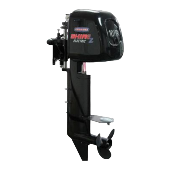
- Page 1 ORIGINAL INSTRUCTION ELECTRIC OUTBOARD MOTOR OPERATORS MANUAL For the following engine models: 10HP 20HP RDG603A74 - Issue 4...
- Page 2 SAFETY Barrus is concerned for your safety. We use safety statements throughout the manual to call your attention to the potential hazards associated with the operation of your electric propulsion outboard. Follow the precautions listed throughout the manual before operation, during operation and during servicing/maintenance procedures for your safety, the safety of others and to protect the performance of your engine.
- Page 3 Engine Details Engine Model Number: Engine Serial Number: Please enter your engine model number and serial number in the space provided above. Please quote the engine identification number during any enquiry or when ordering spare parts. Information about the engine serial number and its location on the engine can be found in SECTION 2 of the manual.
- Page 4 Engine specifications, Benefits and Optional extras Specifications: • 48 Volt electric outboard • CE Marked • UKCA Marked • Water cooled brushless electric motor • Variable speed • Adjustable leg length from short to long shaft • Outboard tilt lock •...
- Page 5 IF A TRANSFER OF TITLE OCCURS, IT MUST ALWAYS BE HANDED OVER TO THE NEW OWNER. Thank you for purchasing this electric outboard motor from Barrus. This manual has been compiled to help you to operate your outboard and its associated parts with safety and pleasure.
- Page 6 Barrus. CONDITIONS THAT MUST BE MET IN ORDER TO OBTAIN WARRANTY COVERAGE Warranty coverage is only available from Barrus or an authorised dealer in the country in which the sale occurred. Routine maintenance outlined in the Owner’s Manual must be performed using genuine parts (such as belt tension gauges) in order to maintain warranty coverage.
-
Page 7: Table Of Contents
Index Page SECTION 1 – Safety Precautions..................10 General ........................10 Lifting ........................10 Rotating Parts ......................10 Propeller ........................11 Electrics ........................11 Batteries ........................11 Safety Lanyard ......................12 Motor Overload ......................13 Modifications ......................13 Boat .......................... 13 Passenger Training .................... - Page 8 Battery Features (EB-4830 / EB-4850) ..............28 Lithium Ion Polymer (LiFePO4) Batteries Precautions (EB-4830 / EB-4850).... 31 Lithium Ion Polymer (LiFePO4) Batteries Warnings (EB-4830 / EB-4850) ....31 Battery Re-Booting ....................32 Battery Type Selection ....................32 Anderson Type Connectors ..................32 Battery Installation ....................
- Page 9 Shipping Weight and Packaging Dimensions ............52 Outboard Dimensions ....................54 SECTION 9 – System Protection Characteristics ............56 SECTION 10 – Spare Parts ....................58 SECTION 11 – Security Products ..................63 STAZO Nutlock ......................63 STAZO Security Chain....................63 STAZO Bracket Nut ....................
-
Page 10: Section 1 - Safety Precautions
SECTION 1 – Safety Precautions 1. General NOTICE: NEVER PERMIT ANYONE TO OPERATE THE OUTBOARD WITHOUT PROPER TRAINING. Ensure that the engine battery isolator switch is in the off position before connecting the battery, carrying out any maintenance or repairs. Also, when the outboard is not in use. -
Page 11: Propeller
The outboard and its accessories are not intended to be put into operation until they are integrated into the boat as a whole. The top cowl must always be fitted whilst the motor is running. 4. Propeller CAUTION • The propeller has sharp edges which can cause injury even when it is stationary. If there is someone in the water near the motor, it must be switched off. -
Page 12: Safety Lanyard
WARNING: BURN HAZARD! BATTERIES CONTAIN SULPHURIC ACID. NEVER ALLOW BATTERY FLUID TO COME IN CONTACT WITH SKIN, EYES OR CLOTHING. SEVERE BURNS COULD RESULT. MAKE SURE THE CORRECT PERSONAL PROTECTION EQUIPMENT IS WORN. • Batteries can produce explosive gases; keep sparks and flames away from the battery. NO SMOKING •... -
Page 13: Motor Overload
Figure 1: Safety Lanyard The outboard will not operate if the safety lanyard is not in place. Ensure there is a spare one on board the boat and that passengers know where it is located. 8. Motor Overload • If the motor is excessively overloaded (by either extended running at high speed or using a propeller which is too big for the application) the motor will stop. -
Page 14: Terminal Crimping
12. Terminal Crimping Ensure that a professional type crimping tool is used for crimping all heavy-duty cable connections. Failure to do so can result in poor performance, system failure, terminal overheating or in some cases melting of plastic terminal plugs or even fires. 13. -
Page 15: Section 2 - Component Identification
SECTION 2 – Component Identification 1. Tiller Control Model Description* Engine Cowl Tiller Control Transom Mounting Bracket Anti-Cavitation Plate Prop Shaft Casing Propeller Skeg Anode Figure 2: Tiller Controlled Outboard 2. Tiller Control Description* Speed Control Twist Grip Direction Display Safety Lanyard Mode Switch On/Off Power Button... -
Page 16: Remote Control Model (Option)
3. Remote Control Model (Option) Description* Steering Wheel Speed and Direction Control Lever Steering Cable Electric Outboard Figure 4: Remote Controlled Outboard Note: A number of optional extras may be fitted to the engines, that are not shown here. 4. Speed and Direction Control Lever (Option) Description* Safety Lock Button Control Grip... -
Page 17: Section 3 - Installation
SECTION 3 – Installation NOTICE: REFER TO THE BARRUS MANUAL PRIOR TO INSTALLING THE ENGINE. 1. Unpacking the Outboard Motor • The outboard motor will arrive in a wooden box. Section 8.3 details shipping weight and packaging dimensions. Use suitable personal protective equipment for unboxing. - Page 18 • Check to make sure the following parts are in the box: 1. Outboard Motor 2. Anderson Type Cable Connector (Qty 1) 3. Safety Lanyard 4. Transom Mounting Bolts and Tools 5. Speed and Direction Control Lever and Steering Kit (Remote Steering Only) Figure 9: Items in the wooden box Note: The outboard does not arrive as pictured above.
- Page 19 7. M12 Nuts 8. Steering Arm Right 9. Washers (2 Sizes) 10. R- Clips 11. Steering extension 12. Steering Spacer 13. Steering Arm Bracket 14. Shifter Mounting Bracket Figures 10 & 11: Ridged Steering Set up (Left) and Flexy Steering Set up (Right) •...
-
Page 20: Filling Outboard Motor With Coolant
rigidity required from the system. • The rigid set up (Figure 10) uses parts 12 and 13 in the steering kit list and attaches to the motor in two places. • The flexy set up (Figure 11) uses the existing steering bracket that is also used for the tiller control. -
Page 21: Adjusting The Outboard Motor Transom Height
• Refit the coolant cap to the outboard motor, making sure it is fully tightened. *Note: The S06 takes approximately 1.75 litres of antifreeze-water mix to fill, whereas the approximate amounts for the S10 and S20 are 2 and 2.1 litres respectively. 3. -
Page 22: Mounting Of The Outboard Motor
4. Mounting of the Outboard Motor • The outboard needs to be mounted so that the boat is balanced. For single-engine boats mount the outboard motor on the centre line (keel line) of the boat. Centre Line Figure 14: Centre Line (Keel Line) •... -
Page 23: Adjusting The Outboard Steering Lock
• Fit the outboard to the boat, securing with the thumb screws on the transom. • Holes are provided to drill through and enable additional bolts (which must be fitted) to secure the outboard to the transom. Thumb Screws Figure 16: Fitting outboard to boat 5. -
Page 24: Battery Selection
6. Adjusting the Outboard Angle • This is much easier to do before the boat is put into the water. • Remove the R clip from the locking pin. • Remove the locking pin from the transom bracket and adjust the outboard motor to the required angle. -
Page 25: Lithium Ion Polymer (Lifepo4) Batteries
Only one 48V Barrus battery module is required to run the boat at 6- 10hp, a minimum of two are required for 20hp. Additional battery modules can be added to increase the range. - Page 26 Current Draw Figure 20: Amps Display Amp Hours Figure 21: Amp Hours Display Battery Percentage Figure 22: Battery Percentage Display • The battery percentage display acts in a similar way to a fuel gauge, with 100% being full (fully charged) and 0% being empty (discharged). RDG603A74 - Issue 4 Page 26 of 97...
- Page 27 Single 48V 30Ah (Amp Hour) and Single 48V 50Ah Battery Specification 48V/ 30Ah (EB4830) 48V/ 50Ah (EB4850) Weight 16kg 27kg Nominal Voltage Charge cut-off voltage 58 ± 0.5v 58v ± 0.5v Overcharge cut-off voltage Normal charger current 5 Amps 8 Amps Normal charge time 6 Hours 6 Hours...
-
Page 28: Battery Features (Eb-4830 / Eb-4850)
Anderson Type Cable Connection Battery Isolation Switch Figure 23: Battery Connections • The outboard motor voltage is 48v (one EB-4830 or one EB-4850 Lithium Ion battery). • The table below shows the minimum battery and equipment specification required for the different outboard motor models. •... - Page 29 • If any of these situations occur, the battery will simply cut out. The display will disappear. If the battery is reconnected to the charger, plugged into the mains supply and switched on, it will re-boot the battery and turn it back on again. Multi-Plug Connector •...
- Page 30 • Alternatively, the outboard motor can be powered by suitable deep cycle traction batteries, sourced by the customer. • The table below shows the minimum battery and equipment specification required for the different outboard motor models. Minimum Battery Minimum Minimum Battery Model Isolation Switch Cable Size...
-
Page 31: Lithium Ion Polymer (Lifepo4) Batteries Precautions (Eb-4830 / Eb-4850)
Model Battery Supply Battery Speed Battery Usage Capacity Time Available 2.2 knots (2.5mph) 5 hours 8 x 12V 65Ah Deep EZ-S10T/R Cycle AGM Traction 130Ah at 48V 3.2 knots (3.7mph) 3 hours 20 mins Battery 4.2 knots (4.8mph) 1 hour •... -
Page 32: Battery Re-Booting
• Take care when transporting the battery, ensuring not to store it with metal objects. • Do not directly solder the battery or remove the protective casing. • Dispose of batteries according to approved regulations. 12. Battery Re-Booting • If the battery is stored for a long period of time it may switch off internally. Or if the battery is over discharged it will trip out and switch off. -
Page 33: Battery Installation
• The Part numbers for the Anderson type connectors are RDG206A48 (S06 and S10) and RDG206A52 (S20) (See Section 10 – Spare Parts) *Note: See Section 1 – 12 safety precautions referring to terminal crimping. 15. Battery Installation • Ensure the batteries are stored in a well-ventilated compartment, that complies with the requirements of the R.C.D (recreational craft directive) or other appropriate regulations. -
Page 34: Connecting Speed And Direction Control Lever (Option)
17. Connecting Speed and Direction Control Lever (Option) • The outboards are available either as tiller operation or as an inboard with remote shift/control. These either come as standard or can be fitted as an option. • The plug on the Control Lever is connected to the plug on the outboard motor (Figure 28). -
Page 35: Section 4 - Operation
SECTION 4 – Operation NOTICE: REFER TO THE BARRUS MANUAL PRIOR TO OPERATING THE ENGINE. NOTICE: THE OUTBOARD MOTOR WILL REQUIRE COOLANT BEING ADDED PRIOR TO BEING USED FOR THE FIRST TIME. PLEASE REFER TO: SECTION 3 – Installation 1. General •... -
Page 36: Starting Procedure (Outboard Motor With Tiller Control)
2. Starting Procedure (Outboard Motor with tiller control) • Attach the magnetic safety lanyard to the tiller arm of the outboard (Figure 29). Figure 29: Safety Lanyard attached to the stop switch • Attach the other end of the safety lanyard to the operator’s life jacket or leg. The outboard will not operate if the safety lanyard is not attached. -
Page 37: Starting Procedure (Outboard Motor With Speed And Direction Control Lever)
3. Starting Procedure (Outboard motor with speed and direction control lever) • Ensure that the lever is in the neutral position. • Attach the safety lanyard to the control lever connected to the outboard (Figure 30). Locking Safety Button Safety Lanyard Power (on/ off) Switch Figure 30: Safety Lanyard attached to control lever... -
Page 38: Stopping Procedure (Outboard Motor With Tiller Control)
Figure 31: Speed and Direction Control Lever in forward position 4. Stopping Procedure (Outboard Motor with tiller control) • Put the speed of the motor to the neutral position using the speed control twist grip. This will stop the propeller. •... -
Page 39: Tilting The Electric Outboard
6. Tilting the Electric Outboard To put the electric outboard in the raised position: Ensure the motor is stopped and the battery disconnected. • Unlock the lower tilt lock mechanism by pulling the handle down and rotating 90˚ to sit as shown in Figure 32. - Page 40 • Reposition the trim pin in the selected position and replace the R clip. To put the electric outboard in the down position: • Tilt the leg slightly up and lift the release lever up (circled, Figure 34). Slowly, tilt the engine down and release the lever.
-
Page 41: Application Downloads And Information
• The speed logged can be shown in either km/h or mph. • This is particularly useful if not using the Barrus (EB-4830 / EB-4850) LiFePO4 batteries as alternative batteries are unlikely to have the visual display gauge on top... - Page 42 • After you have connected the Bluetooth adaptor, replace the cowl. Figures 37 & 38: App Manual Note: Often the motor will appear as “LDMC” or similar on the in-app Bluetooth menu. Note: The app may appear in a different layout on the iPhone version. •...
- Page 43 • The app has the ability to set the 3 modes to different percentages of maximum throttle. The default for each of the three modes is: Economic- 25%, Normal 60% and Sport 100%. These can be altered to the desired percentages at your own discretion.
-
Page 44: Section 5 - Maintenance
SECTION 5 – Maintenance NOTICE: REFER TO THE BARRUS MANUAL PRIOR TO CARRYING OUT ANY MAINTENANCE WORK. WARNING: PRIOR TO CARRYING OUT ANY SERVICE OR MAINTENANCE WORK MAKE SURE THE RELEVANT PERSONAL PROTECTION EQUIPMENT IS WORN. 1. General • The person who is to carry out the maintenance of the outboard motor needs to have the relevant mechanical and electrical competence to do so. -
Page 45: Installing Propeller
3. Installing propeller • Apply Quicksilver 2-4-C Multipurpose Marine Lubricant to the propeller shaft. • Fit the thrust washer and propeller onto the shaft. • Fit the propeller nut and tighten to the correct torque (17Nm – 12.5 lb-ft). • Align the propeller nut with the propeller shaft hole. Insert a new split pin in the hole and bend the ends of the pin. - Page 46 Figure 42: Removal of the threaded plug • Set the gauge to ‘peak’ and push against the belt until the gauge is flush with the side of the leg. Figure 43: Using the tension testing device Engine Model Belt Tension (N) EZ-S06T/R (SHIRE06EZTILLPDI/SHIRE06EZREMPDI) 50-65 EZ-S10T/R (SHIRE10EZTILLPDI/SHIRE10EZREMPDI...
- Page 47 Figure 44: Locating the four motor clamp screws • Then turn the nut to adjust the tension: clockwise to increase the tension, anticlockwise to decrease the tension. Figure 45: Changing the tension of the belt • Before checking the belt tension again, the four motor clamp screws need to be tightened.
- Page 48 6. Prop Shaft Bearing Replacement • The bearings on the prop shaft need to be replaced after 500 hours. Figure 46: Seal Removal Tool • Using the belt tension instructions loosen the belt in the leg. Note: If the belt is not loose the shaft will not come out and belt damage could occur. •...
-
Page 49: Section 6 - Transportation And Storage
SECTION 6 – Transportation and Storage 1. Transporting • When the outboard motor is removed from the boat, lay it down horizontally or put the outboard motor back in the original box. 2. Storage • Store the outboard motor in a well ventilated, dry storage area. •... -
Page 50: Section 7 - Wiring Diagrams
SECTION 7 – Wiring Diagrams 1. Wiring Diagram for Electric Propulsion Outboard Figure 47: Outboard Wiring Diagram (S06/S10) RDG603A74 - Issue 4 Page 50 of 97... - Page 51 Figure 48: Outboard Wiring Diagram (S20) RDG603A74 - Issue 4 Page 51 of 97...
-
Page 52: Section 8 - Technical Data
SECTION 8 – Technical Data 1. Outboard Data Engine Model EZ-S06T/R EZ-S10T/R EZ-S20T/R Output (kW) 10.5 Approximate Equivalent Petrol Engine Power (hp) Nominal Voltage (V) Input Current (A) FOC Controller (Sine Wave) VEC240 VEC300 VEC500 ≥90% ≥90% ≥90% Max Motor Efficiency Max Propeller Speed (r/min) 2800 2800... - Page 53 (SHIRE10EZTILLPDI/ SHIRE10EZREMPDI) EZ-S20T/R 66kg 73cm × 35cm × 93cm (SHIRE20EZTILLPDI/ SHIRE20EZREMPDI) RDG603A74 - Issue 4 Page 53 of 97...
-
Page 54: Outboard Dimensions
4. Outboard Dimensions Figure 49: S06 Drawing RDG603A74 - Issue 4 Page 54 of 97... - Page 55 Figure 50: S10 Drawing RDG603A74 - Issue 4 Page 55 of 97...
- Page 56 Figure 51: S20 Drawing RDG603A74 - Issue 4 Page 56 of 97...
-
Page 57: Section 9 - System Protection Characteristics
SECTION 9 – System Protection Characteristics In the event of the operating system receiving a fault code, the controller will sound out one of the following error codes via a number of beeps. System Protection Feature Description No. of Beeps Battery voltage is higher than default Over–voltage protection value. -
Page 58: Section 10 - Spare Parts
SECTION 10 – Spare Parts Item EZ-S06T/R EZ-S10T/R EZ-S20T/R GM-HPM3000L GM-HPM5000L GM-HPM10KL Motor GM-BP0001- GM-BP0001- GM-BP0002- Motor Pulley S06/S10 S06/S10 Motor Controller GM-VEC72220 GM-VEC72300 GM-VEC72500 GM-CA- Motor Wiring Harness GM-CA-201VEC GM-CA-201VEC 201VEC Fuse GM-FS0001 GM-FS0002 GM-FS0003 Bluetooth Adaptor GM-BL0001 GM-BL0001 GM-BL0001 Laptop Connecting Lead GM-PI-400VEC... - Page 59 Skeg-Rudder RDG401A425 RDG401A425 RDG401A425 Top Cover (Cowl) GM-TC1001 GM-TC1001 GM-TC2001 Cowl Protective Cover GM-BG1001 GM-BG1001 GM-BG2001 Transom Mounting Bracket GM-MBS0001 GM-MBS0001 GM-MBS0001 Transom Bracket RDG117A59 RDG117A59 RDG117A59 Battery Master Switch RDG2199938 RDG2199938 RDG2199938 Anderson Type Connector RDG206A48 RDG206A48 RDG206A52 Anderson Type Connector RDG206A47 RDG206A47 RDG206A47...
- Page 60 Steering Arm Bracket RDG401A456 RDG401A456 RDG401A456 Spacer RDG106A312 RDG106A312 RDG106A312 Quicksilver 2-4-C Multipurpose 92-8M0121966 92-8M0121966 92-8M0121966 Marine Lubricant Throttle Potentiometer GM-110E1305 GM-110E1305 GM-110E1305 Over Centre Latch Assembly GM-CC0001 GM-CC0001 GM-CC0001 Plastic Bush Set GM-PB0001-S GM-PB0001-S GM-PB0001-S Special Tools Item EZ-S06T/R EZ-S10T/R EZ-S20T/R Belt Tension Gauge...
- Page 61 Figure 52: Skeg-Rudder If converting from an inboard petrol or diesel engine (or the existing transom is too thick) there is a transom bracket available. Figure 53: Transom bracket RDG603A74 - Issue 4 Page 61 of 97...
- Page 62 There is available an extended anti-cavitation plate which allows for better steering and simply replaces the existing anti-cavitation plate. Note: The anode will need to be removed from the existing anti-cavitation plate and put onto the new one. Figure 54: Extended Anti-Cavitation Plate RDG603A74 - Issue 4 Page 62 of 97...
-
Page 63: Section 11 - Security Products
SECTION 11 – Security Products Barrus offers a range of security products for the outboard. 1. STAZO Nutlock • Part Number – 42.117.020 • Thick-walled stainless-steel lock • Includes a STAZO plus cylinder and security card • Easy to install Figure 55: STAZO Nutlock 2. -
Page 64: Stazo Bracket Nut
3. STAZO Bracket Nut • Part Number – 42.117.361 – M8 • Stainless steel • Easy installation Figure 57: STAZO Bracket Nut 4. STAZO Outboard Lock • Part Number – 42.117.002 • Solid stainless-steel lock • Dimensions – 40 x 40 x 300mm Figures 58 &... -
Page 65: Talamex Outboard Motor Lock
5. Talamex Outboard Motor Lock • Part Number – 42.130.100 • AISI 316 cylinder lock, anti-rattle • Packed in blister • Dimensions – 300 x 40 x 35mm Figure 60: Talamex Outboard Motor Lock RDG603A74 - Issue 4 Page 65 of 97... -
Page 66: Section 12 - Special Tools
SECTION 12 – Special Tools Barrus offers serval tools to assist dealers and mechanics. 1. Belt Tension Gauge (RDG701A68) • Instructions on use can be found in section 5- maintenance. • This tool can be used to check the tension of the belt. - Page 67 3. Bearing Puller (RDG701A60) • The forward bearing can get stuck in the leg when the prop shaft is removed. • This tool will help remove the bearing easily. Figure 63: Bearing Puller 4. Prop Shaft Removal Tool (RDG701A61 / RDG701A62) •...
- Page 68 5. Motor Front Bearing/Seal Removal Tool (RDG701A69) • Adjustable pin spanner for removal of motor front bearing and front seal. • See Figure 66 for where to use. Figure 65: Motor Front Bearing/Seal Removal Tool Figure 66: How to use Motor Front Bearing/Seal Removal Tool RDG603A74 - Issue 4 Page 68 of 97...
-
Page 69: Section 13 - Declarations
Directive 2012/53/EU. (CE Marking) Name of Engine Manufacturer: Golden Motor LTD Name of Authorised Representative: E.P.Barrus LTD Address: E.P.Barrus LTD, Launton Road, Bicester, Oxon, OX26 4UR, England Name of Notified Body for assessment: Devi Comfort B.V. Address: Vaart 3, 1713GR Obdam, The Netherlands... - Page 70 EN ISO 60204 (2012) Safety of machinery - Electrical equipment of machines BS EN ISO 8848-2017 - Small craft-Remote steering BS EN ISO 16315:2016 - Small craft – Electric propulsion system This declaration of conformity is issued under the sole responsibility of the manufacturer. I declare on behalf of the engine manufacturer that the engine(s) [is (are) in conformity with the type(s) for which above mentioned EC type-examination or type approval certificate(s) has (have) been issued and] will meet the requirements of Directive 2013/53/EU when installed in a recreational craft, in accordance with the engine manufacturer’s...
-
Page 71: Declaration Of Conformity For Recreational Craft Propulsion Engine With The Requirements Of The Recreational Craft Regulations 2017 (Ukca Marking)
Recreational Craft Regulations 2017 (UKCA Marking) Name of Engine Manufacturer: Golden Motor LTD Name of Authorised Representative: E.P.Barrus LTD Address: E.P.Barrus LTD, Launton Road, Bicester, Oxon, OX26 4UR, England Name of Notified Body for Assessment: Not Applicable (Self Assessment) Description of Engine(s) and Essential Requirements... - Page 72 ISO 8848-2017 - Small craft-Remote steering This declaration of conformity is issued under the sole responsibility of the manufacturer. I declare on behalf of the engine manufacturer that the engine(s) [is (are) in conformity with the type(s) for which above mentioned EC type-examination or type approval certificate(s) has (have) been issued and] will meet the requirements of the Recreational Craft Regulations 2017 when installed in a recreational craft, in accordance with the engine manufacturer’s supplied instructions and that this (these) engine(s) must not be put into service until the...
-
Page 73: Lifep04 Battery Tuv Safety Data Sheet
3. LiFEP04 Battery TUV Safety Data Sheet RDG603A74 - Issue 4 Page 73 of 97... - Page 74 RDG603A74 - Issue 4 Page 74 of 97...
- Page 75 RDG603A74 - Issue 4 Page 75 of 97...
- Page 76 RDG603A74 - Issue 4 Page 76 of 97...
- Page 77 RDG603A74 - Issue 4 Page 77 of 97...
- Page 78 RDG603A74 - Issue 4 Page 78 of 97...
- Page 79 RDG603A74 - Issue 4 Page 79 of 97...
- Page 80 RDG603A74 - Issue 4 Page 80 of 97...
- Page 81 RDG603A74 - Issue 4 Page 81 of 97...
- Page 82 RDG603A74 - Issue 4 Page 82 of 97...
- Page 83 RDG603A74 - Issue 4 Page 83 of 97...
- Page 84 RDG603A74 - Issue 4 Page 84 of 97...
- Page 85 RDG603A74 - Issue 4 Page 85 of 97...
- Page 86 RDG603A74 - Issue 4 Page 86 of 97...
- Page 87 RDG603A74 - Issue 4 Page 87 of 97...
- Page 88 RDG603A74 - Issue 4 Page 88 of 97...
- Page 89 RDG603A74 - Issue 4 Page 89 of 97...
- Page 90 RDG603A74 - Issue 4 Page 90 of 97...
- Page 91 RDG603A74 - Issue 4 Page 91 of 97...
- Page 92 RDG603A74 - Issue 4 Page 92 of 97...
- Page 93 RDG603A74 - Issue 4 Page 93 of 97...
- Page 94 RDG603A74 - Issue 4 Page 94 of 97...
- Page 95 RDG603A74 - Issue 4 Page 95 of 97...
- Page 96 Blank Page RDG603A74 - Issue 4 Page 96 of 97...
- Page 97 Serial Number: Rental Use: Yes/No Location: Date of Delivery: Owner signature: Dealer signature: Please return this form by post to: Special Products Division Warranty E. P. Barrus Ltd Glen Way, Launton Road, Bicester, Oxfordshire, OX26 4UR OR by email to: Richard.Cooke@barrus.co.uk Please keep a copy of the form for your own records.
Need help?
Do you have a question about the ShireZ Electric 6HP and is the answer not in the manual?
Questions and answers