
Related Manuals for EURONORM JI500

Summary of Contents for EURONORM JI500
- Page 1 Frequency Drive JI500 Manual www.euronormdrives.com info@euronorm.nl +31 (0) 252 228850...
-
Page 2: Table Of Contents
V-11 Air compressor constant pressure control (Sensor for two-wire pressure transmitter) ........95 V-12 Frequency reference mode(External potentiometer, keyboard encoder) switching ..........96 Modified record ............................97 Hub van Doorneweg 8 • 2171 KZ Sassenheim – NL • +31(0)252 228850 • +31(0)252 228235 • sales@euronorm.nl • euronormdrives.com... -
Page 3: Foreword
1 1 . . F F o o r r e e w w o o r r d d Thank you for choosing JI500 series fundamental form frequency inverter. Thank you for choosing JI500 series fundamental form frequency inverter. -
Page 4: Inspection And Safety Precautions
3. Inspection and safety precautions Euronorm frequency inverters have been tested and inspected before leaving factory. After purchasing, please check if its pack- age is damaged due to careless transportation, and if the specifications and model of the product are consistent with your order requirements. -
Page 5: Precautions
5 It is required to add the optional input filter attachment so as to meet CE standards. Hub van Doorneweg 8 • 2171 KZ Sassenheim – NL • +31(0)252 228850 • +31(0)252 228235 • sales@euronorm.nl • euronormdrives.com... -
Page 6: Scope Of Applications
The safe operation of this unit depends on proper transport, installation, operation and maintenance! Hub van Doorneweg 8 • 2171 KZ Sassenheim – NL • +31(0)252 228850 • +31(0)252 228235 • sales@euronorm.nl • euronormdrives.com... -
Page 7: Standard Specifications
4. Standard specifications 4.1 Technical specifications Rated output Rated input Rated output Model Adaptive motor(kW) power(kW) current(A) current(A) AC 1PH 220V(-15%)~240V(+10%) JI500 0R4G1 JI500 0R7G1 0.75 0.75 JI500 1R5G1 JI500 2R2G1 JI500 004G1 JI500 5R5G1 AC 3PH 220V(-15%)~240V(+10%) JI500 0R4G2 JI500 0R7G2 0.75... - Page 8 Rated output Rated input Rated output Model Adaptive motor(kW) power(kW) current(A) current(A) JI500 200G3/220F3 200/220 385/430 380/426 200/220 JI500 220G3 JI500 250F3 JI500 250G3/280F3 250/280 468/525 465/520 250/280 JI500 280G3 JI500 315F3 JI500 315G3/355F3 315/355 590/665 585/650 315/355 JI500 355G3/400F3...
-
Page 9: Special Customized Product Specifications
400/450 Note: (1) JI500 frequency converter JI500 132G3 / JI500 160F3 ~ JI500 630G3 with “R” indicates DC reactor, such as JI500 160G3R,JI500 160G4R. (2) The correct selection method of frequency converter is: the rated output current of frequency converter is greater than or equal to the rated current of motor, and the overload capacity is considered;... -
Page 10: Standard Specifications
The current limiting algorithm is used to reduce the inverter over current Quick current limiting probability, and improve whole unit anti-interference capability. Timing control Timing control function: Time setting range(0m~6500m) Hub van Doorneweg 8 • 2171 KZ Sassenheim – NL • +31(0)252 228850 • +31(0)252 228235 • sales@euronorm.nl • euronormdrives.com... - Page 11 Key lock and function selection Lock part or all of keys, define the function scope of some keys to prevent misuse. Hub van Doorneweg 8 • 2171 KZ Sassenheim – NL • +31(0)252 228850 • +31(0)252 228235 • sales@euronorm.nl • euronormdrives.com...
- Page 12 3000m Protection level IP20 Product adopts safety standards. IEC61800-5-1 Product adopts EMC standards. IEC61800-3 Cooling method Forced air cooling Hub van Doorneweg 8 • 2171 KZ Sassenheim – NL • +31(0)252 228850 • +31(0)252 228235 • sales@euronorm.nl • euronormdrives.com...
-
Page 13: Keyboard
• Slow flashing: in the motor tunning status • Quick flashing: in the fault status frequency unit current unit HzAV voltage unit speed unit percentage Hub van Doorneweg 8 • 2171 KZ Sassenheim – NL • +31(0)252 228850 • +31(0)252 228235 • sales@euronorm.nl • euronormdrives.com... -
Page 14: Description Of Operation Panel Keys
3-5-1. Instructions on viewing and modifying function code JI500 inverter’s operation pane is three levels menu for parameter setting etc.Three levels: JI500 inverter’s operation pane is three levels menu for parameter setting etc.Three levels: function parameter group (Level 1)→function code(level 2)→function code setting(level 3). The function parameter group (Level 1)→function code(level 2)→function code setting(level 3). -
Page 15: Examples Of Parameter Settings
5.5 Examples of parameter settings 5.5.1 Instructions on viewing and modifying function code JI500 inverter’s operation pane is three levels menu for parameter setting etc. Three levels: function parameter group (Level 1)→function code(level 2)→function code setting(level 3). The operation is as following:... - Page 16 Choose vector control, one must input the motor’s parameters in the nameplate accurately before running the inverter. JI500 series frequency inverter will match the motor’s standard parameters according to its nameplate. The vector control is highly depend on motor’s parameters. The parameters of the controlled motor must be inputted accurately for the good control performance.
-
Page 17: Installation And Commissioning
Fig. 6.2: JI500 Series Each power level installation space requirement JI500 Series frequency inverter heat radiator circulated from bottom to top, when more than one inverter work together, usually mounted side by side. In the case of the need to install them by upper and lower rows, due to the heat of the lower inverters rising to the upper equipment, fault maybe caused, heat insulation deflector and other objects to be installed. -
Page 18: Wiring Diagram
1. 0.75~4kW G3 main circuit terminal (Moulded shell series) 0.75~4kW G3 main circuit terminal 2. 5.5~11kW G3 main circuit terminal (Moulded shell series) 5.5~11kW G3 main circuit terminal Hub van Doorneweg 8 • 2171 KZ Sassenheim – NL • +31(0)252 228850 • +31(0)252 228235 • sales@euronorm.nl • euronormdrives.com... - Page 19 Figure 4-9:37~45kW G3B and 045G3 main circuit terminal 7.55~75kW G3B main circuit terminal 37~45kW G3B and 045G3 main circuit terminal Hub van Doorneweg 8 • 2171 KZ Sassenheim – NL • +31(0)252 228850 • +31(0)252 228235 • sales@euronorm.nl • euronormdrives.com...
- Page 20 9 93~160kW G3 main circuit terminal 93~160kW G3 main circuit terminal 10 160kW F3 main circuit terminal 160W F3 main circuit terminal Hub van Doorneweg 8 • 2171 KZ Sassenheim – NL • +31(0)252 228850 • +31(0)252 228235 • sales@euronorm.nl • euronormdrives.com...
- Page 21 Note: P/+ standard is circuit standard configuration is for the shorted state; if external DC reactor is connected, firstly disconnect and then reconnect. Hub van Doorneweg 8 • 2171 KZ Sassenheim – NL • +31(0)252 228850 • +31(0)252 228235 • sales@euronorm.nl • euronormdrives.com...
- Page 22 Figure 4-17:Schematic diagram of varistor switch (VDR) and safety capacitor switch (EMC) Schematic diagram of varistor switch (VDR) and safety capacitor switch (EMC) Hub van Doorneweg 8 • 2171 KZ Sassenheim – NL • +31(0)252 228850 • +31(0)252 228235 • sales@euronorm.nl • euronormdrives.com...
-
Page 23: Control Circuit Terminals
1. Input range:DC-10~+10V Analog input 2. Voltage input impedance:20kΩ; terminal 3 3. AI3 reference potential can be GND or -10V. Hub van Doorneweg 8 • 2171 KZ Sassenheim – NL • +31(0)252 228850 • +31(0)252 228235 • sales@euronorm.nl • euronormdrives.com... - Page 24 COM jump line decide whether to connect PE, improve the inverter anti-interference interface COM Terminal Consistent with the COM function on the terminal line. interface Hub van Doorneweg 8 • 2171 KZ Sassenheim – NL • +31(0)252 228850 • +31(0)252 228235 • sales@euronorm.nl • euronormdrives.com...
- Page 25 Note: using an external power supply, PLC and 24 v jumper cap must be removed, otherwise it will damage the product. it will damage the product. 4-5.Wiring Precautions Hub van Doorneweg 8 • 2171 KZ Sassenheim – NL • +31(0)252 228850 • +31(0)252 228235 • sales@euronorm.nl • euronormdrives.com Danger...
-
Page 26: Wiring Precautions
MCC1 PI500 inverter MCC2 MCC1 & MCC2 interlock ac contactor Figure 4-22:Spare Circuit electrical diagram Spare Circuit electrical diagram Hub van Doorneweg 8 • 2171 KZ Sassenheim – NL • +31(0)252 228850 • +31(0)252 228235 • sales@euronorm.nl • euronormdrives.com... -
Page 27: Commissioning
• Connect power supply to the R, S and T terminals of the inverter. • Select the appropriate operation control method. Hub van Doorneweg 8 • 2171 KZ Sassenheim – NL • +31(0)252 228850 • +31(0)252 228235 • sales@euronorm.nl • euronormdrives.com... -
Page 28: Function Parameter
To set motor parameter Function code management To set password, parameter initialization and parameter group display Fault query Fault message query Hub van Doorneweg 8 • 2171 KZ Sassenheim – NL • +31(0)252 228850 • +31(0)252 228235 • sales@euronorm.nl • euronormdrives.com... - Page 29 Input voltage value before AI3 linear correction 0.01V d0.40 Reserve Motor temperature inspection d0.41 PT100 inspect motor temperature value 0 °C function3 Hub van Doorneweg 8 • 2171 KZ Sassenheim – NL • +31(0)252 228850 • +31(0)252 228235 • sales@euronorm.nl • euronormdrives.com...
- Page 30 F0.14 Deceleration time 1 0.00s ~ 6500s on models 0:1 second; 1:0.1 second; ★ F0.15 Ac/Deceleration time unit 2:0.01 second Hub van Doorneweg 8 • 2171 KZ Sassenheim – NL • +31(0)252 228850 • +31(0)252 228235 • sales@euronorm.nl • euronormdrives.com...
- Page 31 The function make use of terminal for fault reset. It has same function with RESET key on the keyboard. Fault reset (RESET) This function can be used to realize remote fault reset. Hub van Doorneweg 8 • 2171 KZ Sassenheim – NL • +31(0)252 228850 • +31(0)252 228235 • sales@euronorm.nl • euronormdrives.com...
- Page 32 When the terminal is active, the PID integral adjustment function is paused, but the proportion and PID integral pause differential adjustments of PID are still valid. Hub van Doorneweg 8 • 2171 KZ Sassenheim – NL • +31(0)252 228850 • +31(0)252 228235 • sales@euronorm.nl • euronormdrives.com...
- Page 33 F1.30 DI filter time 0.000s~1.000s 0.010s ☆ F1.31 AI1 filter time 0.00s~10.00s 0.10s ☆ F1.32 AI2 filter time 0.00s~10.00s 0.10s Hub van Doorneweg 8 • 2171 KZ Sassenheim – NL • +31(0)252 228850 • +31(0)252 228235 • sales@euronorm.nl • euronormdrives.com...
- Page 34 Keyboard Encoder control 0: Stop keep; 1: Stop order zero clear 2: Stop over zero clear Hundred bits: Reserve Thousand bits: Reserve Hub van Doorneweg 8 • 2171 KZ Sassenheim – NL • +31(0)252 228850 • +31(0)252 228235 • sales@euronorm.nl • euronormdrives.com...
- Page 35 When the inverter’s accumulated power on time (F6.08) over F7.20 the set time, Cumulative power-on time arrival the output ON signal. Hub van Doorneweg 8 • 2171 KZ Sassenheim – NL • +31(0)252 228850 • +31(0)252 228235 • sales@euronorm.nl • euronormdrives.com...
- Page 36 50.00kHz ☆ F2.10 SPB switching quantity output delay time 0.0s~3600.0s 0.0s ☆ F2.11 Relay 1 output delay time 0.0s~3600.0s 0.0s Hub van Doorneweg 8 • 2171 KZ Sassenheim – NL • +31(0)252 228850 • +31(0)252 228235 • sales@euronorm.nl • euronormdrives.com...
- Page 37 3~8: V/F relationship curve between linear V/F and square V/F. ★ F4.01 Torque boost 0.0%(Automatic torque boost) 0.1~30% 0.0% Hub van Doorneweg 8 • 2171 KZ Sassenheim – NL • +31(0)252 228850 • +31(0)252 228235 • sales@euronorm.nl • euronormdrives.com...
- Page 38 Excitation regulator integral gain 0~60000 1300 ☆ F5.14 Torque regulator proportional gain 0~60000 2000 ☆ F5.15 Torque regulator integral gain 0~60000 1300 Hub van Doorneweg 8 • 2171 KZ Sassenheim – NL • +31(0)252 228850 • +31(0)252 228235 • sales@euronorm.nl • euronormdrives.com...
- Page 39 QUICK key function selection 3: FWD/RVS switchover 4: Clear-up UP/DOWN setting 5: Free stop 6: Running command given in sequence Hub van Doorneweg 8 • 2171 KZ Sassenheim – NL • +31(0)252 228850 • +31(0)252 228235 • sales@euronorm.nl • euronormdrives.com...
- Page 40 ☆ F7.39 Random arrivals current 2 width 0.0%~300.0% (Rated motor current) 0.0% ☆ F7.40 Module temperature arrival 0 °C~100°C 75°C Hub van Doorneweg 8 • 2171 KZ Sassenheim – NL • +31(0)252 228850 • +31(0)252 228235 • sales@euronorm.nl • euronormdrives.com...
- Page 41 Detection value for too large speed deviation 0.0~50.0% (Maximum frequency) 20.0% ☆ F8.16 Detection time for too large speed deviation 0.0~60.0s 5.0s Hub van Doorneweg 8 • 2171 KZ Sassenheim – NL • +31(0)252 228850 • +31(0)252 228235 • sales@euronorm.nl • euronormdrives.com...
- Page 42 0: Two way hall; 1: Three way Hall Three way hall operation short circuit to ground ☆ F8.38 0~100% (Relative motor current) threshold Hub van Doorneweg 8 • 2171 KZ Sassenheim – NL • +31(0)252 228850 • +31(0)252 228235 • sales@euronorm.nl • euronormdrives.com...
- Page 43 0: Invalid ☆ Fb.08 Random PWM depth 1~10: PWM carrier frequency random depth ☆ Fb.09 Deadband time adjustment 100%~200% 150% Hub van Doorneweg 8 • 2171 KZ Sassenheim – NL • +31(0)252 228850 • +31(0)252 228235 • sales@euronorm.nl • euronormdrives.com...
- Page 44 0 stage running time T0 0.0s(h)~6500.0s(h) 0.0s(h) ☆ E1.19 0 stage ac/deceleration time selection ☆ E1.20 1 stage running time T1 0.0s(h)~6500.0s(h) 0.0s(h) Hub van Doorneweg 8 • 2171 KZ Sassenheim – NL • +31(0)252 228850 • +31(0)252 228235 • sales@euronorm.nl • euronormdrives.com...
- Page 45 4: High-speed pulse setting 5: PID control setting 6: Keyboard set frequency (F0.01) setting, UP/DOWN can be modified 7: Analog AI3 given Hub van Doorneweg 8 • 2171 KZ Sassenheim – NL • +31(0)252 228850 • +31(0)252 228235 • sales@euronorm.nl • euronormdrives.com...
- Page 46 ☆ E2.30 PID stop frequency 0.00Hz~maximum frequency (F0.19) ☆ E2.31 PID checking time 0s~3600s ☆ E2.32 PID checking times 1~500 Hub van Doorneweg 8 • 2171 KZ Sassenheim – NL • +31(0)252 228850 • +31(0)252 228235 • sales@euronorm.nl • euronormdrives.com...
- Page 47 VDO3 output delay time 0.0s~3600.0s 0.0s ☆ E3.20 VDO4 output delay time 0.0s~3600.0s 0.0s ☆ E3.21 VDO5 output delay time 0.0s~3600.0s 0.0s Hub van Doorneweg 8 • 2171 KZ Sassenheim – NL • +31(0)252 228850 • +31(0)252 228235 • sales@euronorm.nl • euronormdrives.com...
- Page 48 1: Reverse Speed feedback PG disconnection detection 0.0s: OFF ★ b0.34 0.0s time 0.1s~10.0s ★ b0.35 Pole-pairs of rotary transformer 1~65535 Hub van Doorneweg 8 • 2171 KZ Sassenheim – NL • +31(0)252 228850 • +31(0)252 228235 • sales@euronorm.nl • euronormdrives.com...
- Page 49 Tens digit: User’s change parameter display selection 0: Not display 1: Display 0: Modifiable ☆ y0.04 Function code modification properties 1: Not modifiable Hub van Doorneweg 8 • 2171 KZ Sassenheim – NL • +31(0)252 228850 • +31(0)252 228235 • sales@euronorm.nl • euronormdrives.com...
- Page 50 • y1.20 Running time of the second fault • y1.21 Reserve y1.22 Reserve y1.23 Frequency of the first fault • Hub van Doorneweg 8 • 2171 KZ Sassenheim – NL • +31(0)252 228850 • +31(0)252 228235 • sales@euronorm.nl • euronormdrives.com...
- Page 51 Output terminal status of the first fault • y1.28 Reserved y1.29 Power-on time of the first fault • y1.30 Running time of the first fault • Hub van Doorneweg 8 • 2171 KZ Sassenheim – NL • +31(0)252 228850 • +31(0)252 228235 • sales@euronorm.nl • euronormdrives.com...
-
Page 52: Troubleshooting
8.1 Fault alarm and countermeasures JI500 inverter system operation in the process of failure, the inverter will protect the motor immediately to stop the output, while the inverter fault relay contact action. Inverter panel will display the fault code, the fault code corresponding to the type of fault and common solutions refer to the following table. - Page 53 2. overcurrent 2. Eliminate overcurrent fault Short-circuit to Err.23 Motor short to ground Replace the cable or motor ground fault Hub van Doorneweg 8 • 2171 KZ Sassenheim – NL • +31(0)252 228850 • +31(0)252 228235 • sales@euronorm.nl • euronormdrives.com...
- Page 54 3. Replace control board or keyboard. 4. Keyboard line is too long, causing the interference. 4. Consult factory, seek help. Hub van Doorneweg 8 • 2171 KZ Sassenheim – NL • +31(0)252 228850 • +31(0)252 228235 • sales@euronorm.nl • euronormdrives.com...
-
Page 55: Emc (Electromagnetic Compatibility)
IEC/EN61800-3, and our products are installed and used according to the guideline of the Section 7.3 and can provide good electromagnetic compatibility in general industry environment. Hub van Doorneweg 8 • 2171 KZ Sassenheim – NL • +31(0)252 228850 • +31(0)252 228235 • sales@euronorm.nl • euronormdrives.com... -
Page 56: Emc Directive
3) The surrounding equipment shall be separately grounded, which can avoid the interference caused by the leakage current of the inverter’s grounding wire when common grounding mode is adopted. Hub van Doorneweg 8 • 2171 KZ Sassenheim – NL • +31(0)252 228850 • +31(0)252 228235 • sales@euronorm.nl • euronormdrives.com... - Page 57 2) The filter shall be installed at a place close to the input end of the power supply as much as possible. Hub van Doorneweg 8 • 2171 KZ Sassenheim – NL • +31(0)252 228850 • +31(0)252 228235 • sales@euronorm.nl • euronormdrives.com...
-
Page 58: Dimension
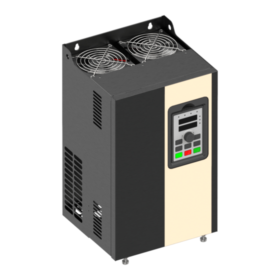
Nameplate Cable inlet Air duct inlet Fig. 9-1: 30kW F3 above Product outside drawing, installation dimension 9.1.2 JI500 series NOTE: 0.75~4kW G3 support Rail installation Fig. 9-2: 0.75~4kW G3Dimension Hub van Doorneweg 8 • 2171 KZ Sassenheim – NL •... - Page 59 Fig. 9-3: 5.5~11kW G3 Dimension Fig. 9-4: 15~22kW G3 Dimension Hub van Doorneweg 8 • 2171 KZ Sassenheim – NL • +31(0)252 228850 • +31(0)252 228235 • sales@euronorm.nl • euronormdrives.com...
- Page 60 Output Dimension (mm) installation Weight (mm) Model power position (kg) (kW) JI500 0R4G1 72.5 JI500 0R7G1 0.75 JI500 1R5G1 72.5 JI500 2R2G1 JI500 004G1 JI500 5R5G1 JI500 7R5G1 2) Outline dimension drawing and installation dimension of three phase 220 V AC...
- Page 61 4) Three phase 480v AC outline dimension drawing and installation dimension Guide rail Installation Output Dimension (mm) installation Weight (mm) Model power position (kg) (kW) JI500 0R7G4 0.75 JI500 1R5G4 72.5 JI500 2R2G4 JI500 004G4 72.5 JI500 5R5G4 JI500 7R5G4 JI500 011G4 JI500 011F4 JI500 015F4 JI500 015G4/018F4 15/18.5...
- Page 62 1) Outline dimension drawing and installation dimension of single phase 220 V AC Installation Output Dimension (mm) Weight (mm) Model power (kg) (kW) JI500 011G1 2) Outline dimension drawing and installation dimension of three phase 220 V AC Installation Output Dimension (mm) Weight (mm) Model power (kg)
- Page 63 4) Three phase 480V AC outline dimension drawing and installation dimension Dimension Installation Output Weight (mm) (mm) Model power (kg) (kW) JI500 030F4 JI500 030G4 JI500 037F4 JI500 037G4/045F4 37/45 JI500 045G4 JI500 055F4 JI500 055G4 JI500 075F4 JI500 075G4 JI500 093F4...
- Page 64 JI500 055F4B JI500 055F4N JI500 055G4B JI500 075G4B 9.1.4 JI500 series (With DC reactor base) Fig. 9-7: 132~220kW G3 (With DC reactor and base )Dimension Hub van Doorneweg 8 • 2171 KZ Sassenheim – NL • +31(0)252 228850 • +31(0)252 228235 •...
- Page 65 Outline dimension drawing and installation dimension of three phase 380V AC three phase 480V AC Dimension Installation Output Weight (mm) (mm) Model power (kW) (kg) JI500 132G3R/160F3R 132/160 1020 13*18 JI500 132G4R/160F4R JI500 160G3R/187F3R 160/187 JI500 187G3R/200F3R 187/200 JI500 200G3R/220F3R 200/220...
- Page 66 Note: With the letter “R” means with a DC reactor; product installation rings screw height dimensions: H1 + 15mm. 9.1.5 Keypad dimension drawing JI500 keyboard size: 2-M3 Fig. 9.10: JI500 keyboard size (Size: Mm) Hub van Doorneweg 8 • 2171 KZ Sassenheim – NL • +31(0)252 228850 • +31(0)252 228235 •...
- Page 67 JI500 keyboard size chart: 5- ? 4.2 90° Fig. 9.11: Keyboard size chart (Size: Mm) JI500 keyboard installation opening size: Opening size of external mounting panel Opening panel 126.5*82 T=1.0 1.5mm 82¡ À 0 .2 Mounting panel Fig. 9.12: Keyboard installation opening size chart (Size: Mm) Notes: 1.
-
Page 68: Maintenance And Repair
• Voltage withstand test can not be arbitrarily implemented, it will reduce the life of inverter. Insulation test can be made with the 500-volt megger before using, the insulation resistance shall not be less than 4MΩ. Hub van Doorneweg 8 • 2171 KZ Sassenheim – NL • +31(0)252 228850 • +31(0)252 228235 • sales@euronorm.nl • euronormdrives.com... -
Page 69: Capacitor
• If a general multi-meter is used to measure three-phase output voltage, the reading is not accurate due to the interference of carrier frequency and it is only for reference. Hub van Doorneweg 8 • 2171 KZ Sassenheim – NL • +31(0)252 228850 • +31(0)252 228235 • sales@euronorm.nl • euronormdrives.com... -
Page 70: Options
Cable comprising a layer of copper spiral. Shield tight as possible, that the more tightly the more we can effectively suppress radiated electromagnetic interference. Insulating layer Shield Cable cross section Hub van Doorneweg 8 • 2171 KZ Sassenheim – NL • +31(0)252 228850 • +31(0)252 228235 • sales@euronorm.nl • euronormdrives.com... -
Page 71: Control Cable
. As shown below: Iron box Iron box Metal tube MCCB Noise Noise PI500 AC input Inverter Filter Filter Hub van Doorneweg 8 • 2171 KZ Sassenheim – NL • +31(0)252 228850 • +31(0)252 228235 • sales@euronorm.nl • euronormdrives.com... -
Page 72: Warranty
5. When the products is broken, please complete the form and warranty card, shipping with the failure machine to our company. 6. Dalian Euronorm Technology Co.,Ltd reserve the right to explain the terms of the event. Hub van Doorneweg 8 • 2171 KZ Sassenheim – NL •... -
Page 73: Appendix I Rs485 Communication Protocol
RS232 to RS485 converter Shielded twisted pair RS232 cable 15m at the longest 485 485+ Frequency inverter Figure I-3 Hub van Doorneweg 8 • 2171 KZ Sassenheim – NL • +31(0)252 228850 • +31(0)252 228235 • sales@euronorm.nl • euronormdrives.com... - Page 74 RS485 line must be the same, address must be different. NOTE: The terminal resistor of 485 decides valid or invalid through the control board (No. 485) jumper Hub van Doorneweg 8 • 2171 KZ Sassenheim – NL • +31(0)252 228850 • +31(0)252 228235 • sales@euronorm.nl • euronormdrives.com...
- Page 75 “Inquiry/Command”of master. Here, the master refers to a Personnel Computer(PC), an industrial control device or a programmable logic controller (PLC), etc. and the slave refers to JI500 inverter. Master can communicate with individUal slave, also send broadcasting information to all the lower slaves. For the single “Inquiry/Command”of master, slave will return a signal(that is a response) to master;...
- Page 76 Data address low-order Data content high-order Data content low-order CRC CHK low-order CRC CHK values are to be calculated CRC CHK high-order Hub van Doorneweg 8 • 2171 KZ Sassenheim – NL • +31(0)252 228850 • +31(0)252 228235 • sales@euronorm.nl • euronormdrives.com...
-
Page 77: Check Mode
_ v a l u e = (C r c _ v a l u e > > 1 )^0xa001; else crc_value=crc_value>>1; return(Crc_value); Hub van Doorneweg 8 • 2171 KZ Sassenheim – NL • +31(0)252 228850 • +31(0)252 228235 • sales@euronorm.nl • euronormdrives.com... -
Page 78: Definition Of Communication Parameter Address
For all parameters, you can also use the command code 07H to achieve the function. Hub van Doorneweg 8 • 2171 KZ Sassenheim – NL • +31(0)252 228850 • +31(0)252 228235 • sales@euronorm.nl • euronormdrives.com... - Page 79 0007: Fault reset Inverter read status: (read-only) Status word address Status word function 0001: Forward run 3000 0002: Reverse run 0003: Stop Hub van Doorneweg 8 • 2171 KZ Sassenheim – NL • +31(0)252 228850 • +31(0)252 228235 • sales@euronorm.nl • euronormdrives.com...
- Page 80 0012: Current detection fault 005C: Initial position error 0013: Motor parameter auto tunning fault 005E: Speed feedback error 0014: Encoder/PG card abnormal Hub van Doorneweg 8 • 2171 KZ Sassenheim – NL • +31(0)252 228850 • +31(0)252 228235 • sales@euronorm.nl • euronormdrives.com...
- Page 81 Hub van Doorneweg 8 • 2171 KZ Sassenheim – NL • +31(0)252 228850 • +31(0)252 228235 • sales@euronorm.nl • euronormdrives.com...
- Page 82 1:0.1A The output unit of the current value is used to determine the output current of the communication read output. Hub van Doorneweg 8 • 2171 KZ Sassenheim – NL • +31(0)252 228850 • +31(0)252 228235 • sales@euronorm.nl • euronormdrives.com...
-
Page 83: Appendix Ii How To Use Universal Encoder Expansion Card
II-1 Overview JI500 is equipped with a variety of universal encoder expansion card (PG card), as an optional accessory, it is necessary part for the inverter closed-loop vector control, please select PG card according to the form of encoder output,... - Page 84 PG card 1:1 feedback output B signal Encoder output Z signal PG card 1:1 feedback output Z signal Output 15V/100mA power Shielding terminal Hub van Doorneweg 8 • 2171 KZ Sassenheim – NL • +31(0)252 228850 • +31(0)252 228235 • sales@euronorm.nl • euronormdrives.com...
-
Page 85: Appendix Iii Can Bus Communication Card Use Description
Appendix III CAN bus communication card use description III-1 Overview CAN bus communication card is suitable for all series of JI500 frequency inverters. Protocol details,please refer to “CAN bus communication protocol” document. III-2 Mechanical installation and terminal functions III-2-1 Mechanical installation modes: Figure IV-1: CAN bus communication card’s installation on SCB... -
Page 86: Appendix Iv: Instruction Of Profitbus -Dp Communication Card
Appendix IV: Instruction of Profitbus –DP communication card IV-1 Outline 9KDP1 meet the international standard PROFIBUS fieldbus, Euronorm technology JI500 series inverter use it together to achieve the drive to become a part of fieldbus complete control of real fieldbus. Before using this product, please carefully read this manual. -
Page 87: Appendix V Product Application Case
The full scale of the pressure gauge is 1.0Mpa. If the pressure of the pipe network is required to be constant at 0.4Mpa, The value of E2.01 is 40.0. Hub van Doorneweg 8 • 2171 KZ Sassenheim – NL • +31(0)252 228850 • +31(0)252 228235 • sales@euronorm.nl • euronormdrives.com... -
Page 88: Terminal Block Control Motor Forward And Reverse
The frequency meter is connected to the DA1 and GND terminals of the inverter, and the ammeter is connected to the DA2 and GND terminals. Hub van Doorneweg 8 • 2171 KZ Sassenheim – NL • +31(0)252 228850 • +31(0)252 228235 • sales@euronorm.nl • euronormdrives.com... -
Page 89: Terminal Block Control Forward /Reverse Running Jog
Command source selection Terminal block control (LED on) F1.02 DI3 terminal function selection Forward JOG(FJOG) F1.03 DI4 terminal function selection Reverse JOG(RJOG) Hub van Doorneweg 8 • 2171 KZ Sassenheim – NL • +31(0)252 228850 • +31(0)252 228235 • sales@euronorm.nl • euronormdrives.com... -
Page 90: Multi-Speed Running
Multi-stage command 0 reference 0 ~ 7 selection, according to the site require- E1.51 manner ments to set the corresponding way Hub van Doorneweg 8 • 2171 KZ Sassenheim – NL • +31(0)252 228850 • +31(0)252 228235 • sales@euronorm.nl • euronormdrives.com... -
Page 91: External Potentiometer Speed
Note: F1.42 is used to adjust the rate of change of panel potentiometer rotation frequency. The smaller this value is, the more sensitive the panel potentiometer rotation frequency changes. Hub van Doorneweg 8 • 2171 KZ Sassenheim – NL • +31(0)252 228850 • +31(0)252 228235 • sales@euronorm.nl • euronormdrives.com... -
Page 92: Rise / Fall Control Speed
Used to set terminal UP/DOWN adjustment F1.11 Terminal UP/DOWN change rate 1.00Hz/s frequency, the rate of frequency change. F0.10 UP/DOWN reference Running frequency Hub van Doorneweg 8 • 2171 KZ Sassenheim – NL • +31(0)252 228850 • +31(0)252 228235 • sales@euronorm.nl • euronormdrives.com... -
Page 93: External Analog Speed Control (External 0 ~ 10V Voltage Signal Given)
Terminal block control (LED on) F1.00 DI1 terminal function selection Forward run (FWD) F1.01 DI2 terminal function selection Reverse run(REV) Hub van Doorneweg 8 • 2171 KZ Sassenheim – NL • +31(0)252 228850 • +31(0)252 228235 • sales@euronorm.nl • euronormdrives.com... -
Page 94: External Analog Speed Control (External 0 ~ 20Ma Current Signal Given)
Minimum input for AIC2 0.00V-F0.18 0.00V Note: If external 4 ~ 20mA current signal is given, please set F1.16 = 2.00V. Hub van Doorneweg 8 • 2171 KZ Sassenheim – NL • +31(0)252 228850 • +31(0)252 228235 • sales@euronorm.nl • euronormdrives.com... -
Page 95: Air Compressor Constant Pressure Control (Sensor For Two-Wire Pressure Transmitter)
E2.29 PID automatic deceleration frequency option Valid E2.27 Computing status after PID stop PID stop with computing Hub van Doorneweg 8 • 2171 KZ Sassenheim – NL • +31(0)252 228850 • +31(0)252 228235 • sales@euronorm.nl • euronormdrives.com... -
Page 96: Frequency Reference Mode(External Potentiometer, Keyboard Encoder) Switching
F0.07 superimposed selection switching Note: DI3 and COM connected to an external potentiometer speed control, disconnect the panel potentiometer speed. Hub van Doorneweg 8 • 2171 KZ Sassenheim – NL • +31(0)252 228850 • +31(0)252 228235 • sales@euronorm.nl • euronormdrives.com... -
Page 97: Modified Record
V4.2 5. Add the company’s QR code to the instruction brand 6. Adjust the optimized size of JI500 045G3 / G4 7. Add special customized product specifications, see page 8 for details 9. The models under the same box in Chapter 7 are distinguished according to the voltage level 10. - Page 98 Hub van Doorneweg 8 • 2171 KZ Sassenheim – NL • +31(0)252 228850 • +31(0)252 228235 • sales@euronorm.nl • euronormdrives.com...
- Page 101 www.euronormdrives.com Hub van Doorneweg 8 Sassenheim...
Need help?
Do you have a question about the JI500 and is the answer not in the manual?
Questions and answers