
Related Manuals for Italsea 7CH4Q107

Summary of Contents for Italsea 7CH4Q107
- Page 1 7CH4Q107_E_4 DATE : 28/06/2013 REV. 4.0 7CH4Q107 MICROPROCESSOR FOUR QUADRANT CONTROLLER FOR PM DC MOTORS EXTERNAL PROGRAMMER - USER’S GUIDE -...
- Page 2 28/06/2013 7CH4Q107_E_4 CONTENTS Page 2 INTRODUCTION Page 2 FEAUTURES SAFETY, MODELS Page 2 MECHANICAL DRAWINGS Page 3 INSTALLATION Page 4 Page 5 WIRING DIAGRAM I/O CONNECTOR 16 pin connector Page 6,7 4 pin connector Page 7 power screws Page 7 CONTROLLER SETTING 7PROGLCD HANDHELD PROGRAMMER Page 8...
- Page 3 28/06/2013 7CH4Q107_E_4 INTRODUCTION The controller 7CH4Q107 is a 4 quadrant chopper for PMDC motors powered by battery 24/36V for traction applications. The chopper is equipped with a powerful microprocessor for digital control of the speed, current regulation and failures of the motor ; an efficient diagnostics of the failures and wrong wiring connections, programmability of the main parameters .
-
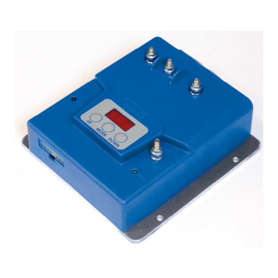
Page 4: Mechanical Drawing
28/06/2013 7CH4Q107_E_4 MECHANICAL DRAWING fig.1... -
Page 5: Installation
28/06/2013 7CH4Q107_E_4 INSTALLATION fig.2 Locate the chopper in a place protected against mechanical abuse, water and dirty. Fix it with all the screws on a metal surface (aluminum if possible) to reduce the heath and so for longer period of work. If during the standard operations the thermal protection is activated very often an additional heath-sink or fan is requested to assure longer periods of work. -
Page 6: Complete Wiring Diagram
28/06/2013 7CH4Q107_E_4 COMPLETE WIRING DIAGRAM... - Page 7 28/06/2013 7CH4Q107_E_4 I/O CONNECTOR 16v Molex connector (Molex p/n.39012160, contacts p/n.39000038) fig.4 Pin 1: HI –POT. INPUT Positive Potentiometer Supply Pin 2: C-POT.INPUT Central Potentiometer, or Voltage (0,5-4,5Vdc) Speed Reference Input Pin 3: LO-POT.INPUT Negative Potentiometer Supply, or Gnd Voltage Speed Reference Input Pin 4: Pin 2:V_MAX (OPTIONAL) Max speed input potentiometer (>100 K ).
- Page 8 28/06/2013 7CH4Q107_E_4 Pin 10: ALARM Connection for the diagnostic Blinking Led indicator (5Vdc-10mA) output : the number of blinks means the alarm type (example 5 blinks means Alarm 5). Pin 11: MODE 1 Default N.O. input to +V battery. Pin 12: FORWARD SWITCH N.O.
- Page 9 28/06/2013 7CH4Q107_E_4 7PROGLCD HANDHELD PROGRAMMER: LCD 16X2: Displays parameters, alarms and measures (description and value). UP Key: Rolls up parameters and increases values. MODE Key: Confirms a selection and the change of value. UP Key: Rolls down parameters and decreases values. fig.8 At power-on, handheld programmer displays the “Tester Mode”...
- Page 10 28/06/2013 7CH4Q107_E_4 HANDHELD TESTER MODE Motor current measure (measure unit=Amperes). MOTOR CURRENT Imot= ## Amps Motor voltage measure (measure unit=Volts). MOTOR VOLTAGE Vmot = ##.# Volts Speed reference voltage (measure unit=Volts); REFERENCE INPUT potentiometer or voltage (0-5V) speed reference. Vref = #.#Volts Internal heat-sink temperature (measure unit C°...
- Page 11 28/06/2013 7CH4Q107_E_4 ALARMS Onboard programmer can display the failures or alarms: in the following table there is the list, the meaning of this alarms, and how to solve the problem. HANDHELD ALARM WHAT TO DO PROGRAMMER Forward switch Put the speed reference ALARM A1 closed at power-on to zero and open the FW...
- Page 12 28/06/2013 7CH4Q107_E_4 HANDHELD ALARM WHAT TO DO PROGRAMMER Check the motor’s wires: Overcurrent 2: if ok, and the controller ALARM A8 short circuit repeats this alarm, OVERCURRENT 2 change it. ALARM A9 Undervoltage. Check battery’s charge. UNDERVOLTAGE Battery voltage upper ALARM A10 Overvoltage.
- Page 13 28/06/2013 7CH4Q107_E_4 HANDHELD PROGRAMMER PARAMETERS Parameter Default Description Default parameters (F0=2) SWITCH-OFF AND ON THE KEY TO CONFIRM Acceleration ramp [s] Reverse deceleration ramp [s] Neutral deceleration ramp [s] Current limit [A] - Imax Backward speed reduction [%] s-en s-en w-w2 Speed reference s-en...
- Page 14 28/06/2013 7CH4Q107_E_4 RESET TO DEFAULT: To reset all the parameters, set 2 and power-off; at the next power-on, the controller will update the defaults settings. DEFAULT: 0 RESET TO DEFAULT MIN: 0 MAX: 2 F0= # GENERAL SETTINGS: ACCELERATION RAMP: Acceleration ramp: time in seconds from stop position to max settled speed.
- Page 15 28/06/2013 7CH4Q107_E_4 FORWARD SPEED: Forward direction maximum speed: value in percent of battery voltage. DEFAULT: 100 FW MAX SPEED MIN: MAX: 100 F22= ###% BACKWARD SPEED: Backward direction maximum speed: value in percent of forward direction max speed. DEFAULT: 60 BACKWARD SPEED MIN: MAX: 100...
- Page 16 28/06/2013 7CH4Q107_E_4 SPEED REFERENCE SETTINGS: Choose “SPEED REFERENCE” SPEED REFERENCE page, and confirm it by “MODE” F10: ########## button - Single-ended potentiometer: potentiometer with two direction switches, - Wigwag1 potentiometer: potentiometer with middle stop position and enable switches, - Wigwag2 potentiometer: potentiometer with middle stop position without enable switches,...
- Page 17 28/06/2013 7CH4Q107_E_4 HANDHELD PROGRAMMER SINGLE-ENDED CALIBRATION: Step 1: Choose “poti course” option, and POTI COURSE confirm it by “MODE” button. Step 2: Choose “tar to set poti course” POTI COURSE option, and confirm it by “UP” button. Step 3: Set the potentiometer or throttle at POTI CALIBR.
- Page 18 28/06/2013 7CH4Q107_E_4 HANDHELD PROGRAMMER WIGWAGS CALIBRATION: Step 1: Choose “single-ended” option, and SPEED REFERENCE confirm it by “MODE” button. F10 = s-en Step 2: Choose “wigwag 1” or “2” or “3” SPEED REFERENCE option, and confirm it by “MODE” F10= button.
- Page 19 28/06/2013 7CH4Q107_E_4 REFERENCE’S DEADBAND: DEFAULT: 2.0 MIN: 0.0 REF. DEADBAND MAX: 10.0 ### mV ELECTROBRAKE OUTPUT SETTING: Controller supplies the electro-brake coil when the motor is running: the coil is powered-off with delay when the speed reference and direction switches are in stop position . Brake ON Brake OFF Time...
- Page 20 28/06/2013 7CH4Q107_E_4 MULTIMODE INPUT SETTINGS: The input on pin 11 of the connector when closed activates a reduced speed or current. This input activates: - maximum motor speed; - maximum motor current. The input is always active. Note: In the controller with handlhed programmer, the input on pin 11 activates DEFAULT: 50 MULTIMODE SPEED MIN:...
-
Page 21: Overload Protection
28/06/2013 7CH4Q107_E_4 OVERLOAD PROTECTION In the programming mode set the rated current and overload time for the motor: DEFAULT: 25 RATED CURRENT MIN: MAX: 40 F17= ## A DEFAULT: 60 OVERLOAD TIME MIN: MAX: 60 F18= ### s The protection will be activated each time the current overcome the value In +10% and the overload time is as shorter as higher is the overload according to the function. - Page 22 28/06/2013 7CH4Q107_E_4 ENGENEERING PROTECTED PARAMETERS IGSL: DEFAULT: MIN: MAX: PGSL: DEFAULT: MIN: MAX: IGCL: DEFAULT: MIN: MAX: PGCL: DEFAULT: MIN: MAX: LPOT: DEFAULT: MIN: MAX: CPOT: DEFAULT: MIN: MAX: CPOT: DEFAULT: MIN: MAX:...
Need help?
Do you have a question about the 7CH4Q107 and is the answer not in the manual?
Questions and answers