
Related Manuals for Italsea 7BL00100

Summary of Contents for Italsea 7BL00100
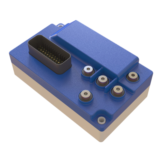
- Page 1 SERVICE MANUAL | rev 1 - 02/2021 7BL00100 MICROPROCESSOR CONTROLLER FOR BRUSHLESS MOTORS English 7BL00100 | page 1...
-
Page 2: Table Of Contents
4a. J7PROGLCD handheld programmer 5. TESTER MODE 6. ALARMS 7. PARAMETERS 8. ELECTROBRAKE DELAY MEANING 9. SPEED REFERENCE CALIBRATION 9a. Single ended calibration 9b. Voltage 0-Max calibration 9c. Wig-wag 1 and 2 calibration 10. BACKWARD SAFETY 11. OVERLOAD PROTECTION page 2 | 7BL00100... -
Page 3: Safety Instructions
It is advisable to build the system with cables of reduced length and to appropriately separate the power cables from the signal ones. If necessary, use shielded cables or external filters to reduce electromagnetic disturbances. 7BL00100 | page 3... -
Page 4: Introduction
2. INTRODUCTION The 7BL00100 is a controller for brushless PM motors for 24V - 48V battery powered industrial-trucks. The controller is equipped with two powerful microcontrollers: main microcontroller for digital control, alarms management, parameters settings; second microcontroller for safety monitoring functions. -
Page 5: 2B. Mechanical Drawing
2b. Mechanical drawing Fix the controller with all the screws on a metal surface (aluminum if possible) to reduce the heat and so for longer working time. 7BL00100 | page 5... -
Page 6: 2C. Wiring Diagram
2c. Wiring diagram page 6 | 7BL00100... -
Page 7: Connections
Hall B or Enc SIN-P input. Pin 31: Hall C or Enc COS-P input. Pin 32: Negative supply (-Battery). Pin 33: Motor temperature probe analog input. Pin 34: Enc CHA or SIN-N input. Pin 35: Enc CHB or COS-N input. 7BL00100 | page 7... -
Page 8: 3B. Power Connections
“DOWN”, then confirm the value with the button “MODE”; at this point you can again move through the parameters. To return to the tester menu push together the buttons “MODE” and “UP”. Modified parameters values are saved when you come back to tester menu. In case of alarm, the programmer displays the alarm number. page 8 | 7BL00100... -
Page 9: Tester Mode
Main connector active inputs (connector pin number); ENC: #,#,#,#,# Hall and encoder status (uppercase, lowercase). HOURMETER Working hours and minutes. #####hrs, ##min MOTOR TEMP. Motor temperature (in °C and °F). ##°C ###°F SOFTWARE RELEASE Software release. 7BL00100_0.0 7BL00100 | page 9... -
Page 10: Alarms
Key off sequence detected Check key connection E² prom fail Check parameters; if the alarm is repeated, change the controller Over-speed Speed too high Hall/Encoder fail Check the hall sensors or the encoder and their connections page 10 | 7BL00100... -
Page 11: Parameters
Backward direction input pull-up/down (see note 4) Enable alarm 01 (see note 5) Enable alarm 03 (see note 5) Enable alarm 04 (see note 5) Enable alarm 12 (see note 5) 30000 Password to access reserved parameters (see note 6) 7BL00100 | page 11... - Page 12 Note 4: Pull Down (PD), Pull Up (PU). Note 5: Enable(ENA), Disable (DIS). Note 6: Password value (ask to your Italsea reference). Note 7: Normal (NOR), Reversed (REV). Note 8: Disabled (DIS), Enabled (ENA), Enabled + Reversed (E+R). page 12 | 7BL00100...
-
Page 13: Electrobrake Delay Meaning
Controller supplies the electro-brake coil when the motor is running: the coil is powered-off with delay when the speed reference and direction switches are in stop position. The value of the delay is regulated by parameter 15. Brake ON Brake OFF Time Motor ON Motor OFF Time BRAKE DELAY 7BL00100 | page 13... -
Page 14: Speed Reference Calibration
CALIBRATION Put the potentiometer in the max backward position; Press the MODE key to confirm. MAXBW POS= ##.#V CALIBRATION Put the potentiometer in the max forward position; Press the MODE key to confirm. MAXFW POS= ##.#V page 14 | 7BL00100... -
Page 15: Backward Safety
Temperature influences the formula, reducing the integration time; if temperature TEMP(t) is higher than 50°C then the following modification is applied to the formula: ∫ VAL(t) = (1.0 + 0.1(TEMP(x) - 50)) (I (x) - I )² dx For example is temperature is 80°C, the time to alarm is reduced 4 times. 7BL00100 | page 15... - Page 16 ITALSEA S.r.l. Via Maestri del Lavoro 1/A | 36078 Valdagno | Vicenza | Italy T +39 0445 431014 | F +39 0445 431048 | italsea@italseasrl.it | italseasrl.it amergroup.it page 16 | 7BL00100...
Need help?
Do you have a question about the 7BL00100 and is the answer not in the manual?
Questions and answers