ADT Pulse DBC845 FHD Wireless Doorbell Camera Manual
- Quick installation manual (25 pages)
Advertisement
Introduction
This section provides information about the Doorbell Camera features, components and capabilities.
Packaging Contents
The following items are included in the package.
- Doorbell Camera x 1

- Two Mounting Brackets (Small Slim & Gang Plate size)
")
- Wedge Kit (15°, 30° Angles)

15° Wedge

30° Wedge

15° Tilt - (No.1) Screw/Anchor x 2
 Screw/Anchor x 2")
- (No.2) Screw x 2
 Screw x 2")
- (No.3) Screw x 2
 Screw x 2")
- (No.4) Screw x 2
 Screw x 2")
- Bubble Level
![]()
- Always On Bracket


")


 Screw/Anchor x 2")
 Screw x 2")
 Screw x 2")
 Screw x 2")

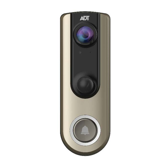
Physical Details
The DBC845 supports both analog and digital chimes within 8-24 AC voltage range. The operation temperature is –4°F to 122°F. (–20°C to 50°C)
(The battery will not be charged when the temperature is < 32°F or discharge when internal temperature is >138°F)

Figure 1-1 Front Panel

Figure 1-2 Rear Panel
Overview
Doorbell/WPS Button has two functions:
WPS Pin Code Mode: When pressed and held 5 seconds, the doorbell camera will be in WPS Pin Code Mode.
Note: When Wi-Fi connection is established, the WPS function is disabled.
Doorbell Mode: Press the button to ring the door chime.
LED Activity & Behavior:
| Doorbell Activity | LED Color | LED Intensity | LED Behavior | Description |
| Power Up | ADT Blue | Medium | Solid | |
| WPS Mode | Green | Medium | Blinking | Time out 2 mins |
| WPS Failure | Red | Medium | Solid for 5 seconds | When WPS pair fails, RED LED solid on fr 5s. Then return back to Network disconnection behavior till someone press WPS button again. |
| Network Connected | ADT Blue | Medium | Solid | After connected to network, then LED goes into Standby mode and related LED behavior while working mode is timeout. |
| Network Disconnection | Red | Medium | Blinking | This priority Is higer than Network Standby mode |
| A/C Disconnected (or other external power resource in the future.) | Red | Medium | Intermittent Blinking in 2s | LED will blink red with 2 second when wired and A/C is not detected At this moment, if the network is connected, the ADT blue is solid, then red LED is edges blinking and then after ADT blue 10s edges m. * When Battery pack replaces AC cable in the feature, this LED behavior will present Battery pack connection status. |
| Standby (Sleep Mode) | ALL | NA | OFF | This priority Is higer than Network connected. |
| Standby to PIR trigger | ADT Blue | Dim | ON | After PIR trigger without button press. |
| Doorbell Button Pressed | ADT Blue | Off-Dim- High | Pulsing for 10 seconds | LED will pulse between OFF(1s) -> dim - > High(1s) intensity while the session is set up. Then return back to Network connection behavior till Doorbell run into standby mode. |
| FW download In Progress | Green | Medium | Spinning | Spinning will indicate FW being downloaded. Once complete, update takes place and doorbell reboots. LED then goes into Power Up mode |
| Factory Reset | Red | Medium | Triple Blink | When Reset pin is held down for 10 secods, once released, LED will blink red triple indicating the start of the reboot/factory reset |
| No Power | Dark | N/A | N/A | LED not powered |
Basic Setup
This section provides information on how to assemble and configure the DBC845 Doorbell Camera for enrollment.
Installation
- Power-Up and Check LED
Turn on the switch on the rear side of the doorbell camera and wait for 20 seconds until the LED turns to flashing red.
![]() Note: The internal battery supports about 40 minutes of operation. If you don't see the camera powering up, please charge the doorbell camera via Micro USB cable with USB charger for 45 min before installation.
Note: The internal battery supports about 40 minutes of operation. If you don't see the camera powering up, please charge the doorbell camera via Micro USB cable with USB charger for 45 min before installation.


Figure 2-1 Power LED - Enroll the Camera in ADT Pulse
This process is described in section 3 ADT Pulse Enrollment. - Mounting the Doorbell Camera
Mount the camera in its final permanent location. Please refer to section Hardware Installation for more details.
 Note: The internal battery supports about 40 minutes of operation. If you don't see the camera powering up, please charge the doorbell camera via Micro USB cable with USB charger for 45 min before installation.

ADT Pulse Enrollment
This section provides instructions for wirelessly enrolling the DBC845 Doorbell Camera into the ADT Pulse network. This process uses WiFi Protected Setup (WPS) with PIN method to wirelessly enroll the HD Camera to gateway via the ADT Pulse portal or Installer App.
Using WPS with PIN
- Power up the camera and wait for the LED to turn flashing red, as described in the previous chapter.
- Launch web browser and log into the Pulse portal or installer app.
- Enter the Manage Devices screen using one of the following methods.
- For the Pulse portal, select the System tab and click Manage Devices.
- For Installer app, click the Pulse Devices link.
- In Manage Devices screen, click Cameras.

Figure 3-1 Clicking "Cameras" Button - Click the Add Using WPS button at the bottom of screen as shown in Figure 3-2.

Figure 3-2 Clicking Add Using WPS Button - Locate the camera PIN number on the label on the rear of the camera. Enter the PIN number in the WPS PIN field as shown in Figure 3-3.

Figure 3-3 Entering the PIN - Click the Continue button to initiate the WPS process.

Figure 3-4 Clicking "Continue" Button - Press the doorbell button, the LED will blink green during WPS process.
![]() Note: This WPS process must be completed within 2 minutes or else it will be timed out. The remaining time is displayed in the upper left portion of the screen.
Note: This WPS process must be completed within 2 minutes or else it will be timed out. The remaining time is displayed in the upper left portion of the screen.

Figure 3-5 Add Camera Using WPS Screen - Once the doorbell camera is enrolled, the Camera Details screen will be displayed. Name the device and select the desired bandwidth & chime type. Click Save after entering or change settings.

Figure 3-6 Saving Camera Details - The newly added device will be shown in the Camera List, then click Go Back at the top left of the screen as shown in Figure 3-7.

Figure 3-7 Clicking Go Back Button - The Manage Devices screen is displayed, click Close.

Figure 3-8 Manage Devices Screen - Click System page to verify the device enrollment.
Figure 3-9 System Screen - Move the doorbell to where it will be mounted and check the LED and site diagnostics to verify Wi-Fi signal strength.
![]() Note: If the Wi-Fi cannot reach the doorbell camera, you will see the LED blinking red. Relocate the Pulse gateway / TS or Cloud Link if possible or add a Wi-Fi repeater to improve the signal strength to the doorbell camera.
Note: If the Wi-Fi cannot reach the doorbell camera, you will see the LED blinking red. Relocate the Pulse gateway / TS or Cloud Link if possible or add a Wi-Fi repeater to improve the signal strength to the doorbell camera. - Factory Reset Instructions:
- Press the doorbell button to wake up the device
- If already enrolled, the device will "ding-dong"
- If not already enrolled, the device will go into WPS mode and blink green
- Press and hold the reset button on the back until you hear a ring (about 10 seconds), then release to start the reset process
- If you don't hear the ring, press the doorbell button again to ensure it is awake and perform step "D" again
- The unit may need to be charged via USB is the battery is too low to perform the factory reset


 Note: This WPS process must be completed within 2 minutes or else it will be timed out. The remaining time is displayed in the upper left portion of the screen.


 Note: If the Wi-Fi cannot reach the doorbell camera, you will see the LED blinking red. Relocate the Pulse gateway / TS or Cloud Link if possible or add a Wi-Fi repeater to improve the signal strength to the doorbell camera.
Hardware Installation
This section provides details for mounting the DBC845 Doorbell Camera.
Installing Hardware
Note: Ensure the camera is configured and enrolled in ADT Pulse before permanently mounting.
- Turn off the breaker circuit before disconnecting legacy doorbell button.

Figure 4-1 Breaker Circuit - Unscrew the legacy doorbell to locate two power wires. (The recommended installation height is between 47-60 inches.)

Figure 4-2 Mounting Location
![]() Note: Check the voltage at the doorbell to ensure voltage is between 9 ~ 24 VAC. If the voltage is DC, then the DC845 does not support this voltage type.
Note: Check the voltage at the doorbell to ensure voltage is between 9 ~ 24 VAC. If the voltage is DC, then the DC845 does not support this voltage type. - Choose the mounting bracket that will cover the hole of the legacy doorbell button. The larger bracket should be used with gang boxes.

Figure 4-3 Choosing Mounting Bracket - Connect the power wires from the existing doorbell to the screw terminals of the bracket.

Figure 4-4 Connecting the power Wires - Secure the bracket with screws (No. 1 or No. 2). Please see Figure 4-5.
Note: Install the anchors if necessary.

Figure 4-5 Installing the Screws - Attach the doorbell camera to the mounting bracket. Make sure the doorbell camera is firmly fixed and working properly.
![]()
To avoid damaging the rubber seal of the pogo pins, please attach the camera to the mounting bracket flush. Mounting bracket should lay flat against the wall. Over torqueing can warp the bracket and cause it to lose contact with pins.

Figure 4-6 Attaching the Camera to the Bracket - Turn on the breaker circuit.
- Check that the chime is working normally by pushing the doorbell button. If the AC wires are not connected properly, the LED will blink Red every 5 seconds.
![]() Note: Please check if the chime sounds, if not, the chime type should be changed in the ADT Pulse portal under Manage Devices.
Note: Please check if the chime sounds, if not, the chime type should be changed in the ADT Pulse portal under Manage Devices.


 Note: Check the voltage at the doorbell to ensure voltage is between 9 ~ 24 VAC. If the voltage is DC, then the DC845 does not support this voltage type.


Using the Wedge Kit (Optional)
If needed, you can mount your doorbell at an angle for better view and motion detection. The wedge kit comes with 3 plates which can be used to tilt the camera forward or sideways by 15/30 degrees.
- Use the two screws (No.1) to install the wedge into the wall. The larger bracket should be used with gang box.
 Step 1")
Figure 4-7 Install the Wedge - Secure the bracket to the wedge with the two screws (No.3 or No. 4).
 Step 2")
Figure 4-8 Attaching the Bracket to the Wedge - Attach the doorbell camera to the bracket.
 Step 3")
Figure 4-9 Attaching the Camera to the Bracket - Apply the Audio Video Surveillance Sticker.
 Step 4")
Figure 4-10 Audio & Video Surveillance Sticker
 Step 1")
 Step 2")
 Step 3")
 Step 4")
Always On Bracket Installation
The Always On bracket can only be installed with mechanical doorbell chimes (AC16V~24V). In this configuration, the doorbell camera will be in always on mode, which brings back the 5 second pre-buffer, connects live view faster, and removes the need for the internal battery to be charged.
- Choose the mounting bracket that will cover the hole of the legacy doorbell button. The larger bracket should be used with gang boxes.

Figure 4-11 Choosing Mounting Bracket - Connect the power wires from the existing doorbell to the screw terminals of the bracket.

Figure 4-12 Connecting the power Wires - Secure the bracket with screws (No.1 or No.2). Please see Figure 4-13.
Note: Install the anchors if necessary.

Figure 4-13 Installing the Screws - Attach the doorbell camera to the mounting bracket. Make sure the doorbell camera is firmly fixed and working properly.
![]() T
T
o avoid damaging the rubber seal of the pogo pins, please attach the camera to the mounting bracket flush. Mounting bracket should lay flat against the wall. Over torqueing can warp the bracket and cause it to lose contact with pins.

Figure 4-14 Attaching the Camera to the Bracket


Appendix
Product Spec
Wireless Doorbell Camera
| Model | DBC845 |
| Dimensions (H x W x D) | 121.15 x 42.25 x 30.8mm |
| Operating Temperature | Mounting Bracket and Battery Pack mode: -20°C to 50°C Always On Bracket mode: • -20ºC to 40ºC (Day Mode) • -20ºC to 35ºC (Night Mode) |
| Storage Temperature | -20°C to 45°C |
| Network Protocols | TCP/IP, HTTP, HTTPS, DHCP, uPnP, NTP, RTP, RTCP, RTSP, DN |
| Wireless | 802.11 b/g/n |
| LED | 1 |
| Microphone | Built-in Microphone |
| Button | Doorbell/WPS Button x 1 Reset button x 1 |
| Speaker | 1 built-in Microphone |
| Power Adapter | USB charger: DC 5V,1A Internal Battery Power: capacity 730mA Charging Temp: 0ºC to 20ºC |
Regulatory Approvals
FCC Statement (US)
This equipment has been tested and found to comply with the limits for a Class B digital device, pursuant to part 15 of the FCC rules. These limits are designed to provide reasonable protection against harmful interference in a residential installation. This equipment generates, uses and can radiate radio frequency energy and, if not installed and used in accordance with the instructions, may cause harmful interference to radio communications. However, there is no guarantee that interference will not occur in a particular installation.
If this equipment does cause harmful interference to radio or television reception, which can be determined by turning the equipment off and on, the user is encouraged to try to correct the interference by one or more of the following measures:
- Reorient or relocate the receiving antenna.
- Increase the separation between the equipment and receiver.
- Connect the equipment into an outlet on a circuit different from that to which the receiver is connected.
- Consult the dealer or an experienced radio/TV technician for help.
To assure continued compliance, any changes or modifications not expressly approved by the party responsible for compliance could void the user's authority to operate this equipment. (Example - use only shielded interface cables when connecting to computer or peripheral devices).
RF Exposure Part
This equipment complies with FCC RF radiation exposure limits set forth for an uncontrolled environment. This transmitter must not be co-located or operating in conjunction with any other antenna or transmitter.
This equipment should be installed and operated with a minimum distance of 20 centimeters between the radiator and your body.
IC Statement (Canada)
This device complies with Industry Canada's licence-exempt RSSs.
Operation is subject to the following two conditions:
(1) This device may not cause interference; and
(2) This device must accept any interference, including interference that may cause undesired operation of the device.
This transmitter must not be co-located or operating in conjunction with any other antenna or transmitter. This equipment should be installed and operated with a minimum distance of 20 centimeters between the radiator and your body.
Exposure
This device meets the exemption from the routine evaluation limits in section 2.5 of RSS102 and users can obtain Canadian information on RF exposure and compliance.

Property of ADT, LLC. Information accurate as of published date and is provided "as is" without warranty of any kind.
©2017ADT LLC dba ADT Security Services. All rights reserved. ADT, the ADT logo, 800 ADT.ASAP and the product/service names listed in this document are marks and/or registered marks. Unauthorized use is strictly prohibited.
Documents / ResourcesDownload manual
Here you can download full pdf version of manual, it may contain additional safety instructions, warranty information, FCC rules, etc.
Download ADT Pulse DBC845 FHD Wireless Doorbell Camera Manual
Advertisement


Need help?
Do you have a question about the Pulse DBC845 and is the answer not in the manual?
Questions and answers