Table of Contents
Advertisement
Quick Links
47BA...B...
Cordless EC angle nutrunner
Series
47
Power
B – Battery
Tool Style
A – Angle
Feature 1 (Data Transmission)
– IrDA
W – WLAN
R – RF868 MHz
F – RF915MHz
For additional product information visit our website at http://www.cooperpowertools.com
N O R T H A M E R I C A
Cooper Power Tools
P.O. Box 1410
Lexington, SC 29071-1410
47 B
A ...
S
Retain for future reference!
Instruction Manual
P1891E/EN
B ... AM3
AM3 - Square 3/8"
Feature 2 (Scanner)
S - Barcode Scanner
E U R O P E
Cooper Power Tools GmbH & Co. OHG
Postfach 30
D-73461 Westhausen
11/06
Attachment
Max. Torque
15 - 15 Nm
28 - 28 Nm
35 - 35 Nm
50 - 50 Nm
Battery
B - 26 V
Advertisement
Table of Contents

Subscribe to Our Youtube Channel
Related Manuals for Cooper Cleco 47BA B Series

Summary of Contents for Cooper Cleco 47BA B Series
- Page 1 For additional product information visit our website at http://www.cooperpowertools.com N O R T H A M E R I C A E U R O P E Cooper Power Tools Cooper Power Tools GmbH & Co. OHG P.O. Box 1410 Postfach 30 Lexington, SC 29071-1410...
- Page 2 Copyright protection Cooper Power Tools reserves the right to modify, supplement or improve the document or the product without prior announcement. This document may not be reproduced in any way, shape or form, in full or parts thereof, or copied to another natural or machine readable language or to a data carrier, whether electronic, mechanical, optical or otherwise without the express permission of Cooper Power Tools.
-
Page 3: Table Of Contents
Contents Safety Presentation of notes................5 Basic requirements for safe working practices ........6 Personnel training................. 6 Personal protective equipment ............. 6 Proper use .................... 7 EMC...................... 7 Noise and vibration ................7 Scope of supply, transport and storage Scope of supply ..................8 Transport .................... - Page 4 LCD display Results display..................19 Status....................20 Set position (only allowed with Linking) ..........21 Communications ................. 22 Diagnostics ..................24 System fault messages............... 29 Maintenance Service schedule ................33 Lubrication Products ................34 Disassembling gear ................34 Disassembling angle attachment............35 Assembling angle attachment.............
-
Page 5: Safety
Safety Safety Presentation of notes Warning notes are identified by a signal word and a pictogram: • The signal word describes the severity and the probability of the impending danger. • The pictogram describes the type of danger. WARNING! Possibly dangerous situation situation for the health of persons. If this warning is not observed, very serious injury may result. -
Page 6: Basic Requirements For Safe Working Practices
Make sure that the sockets are securely inserted. Personnel training All operators must be trained and experienced before operating the 47BA. The 47BA must be repaired by authorized technicians from Cooper Power Tools only. Personal protective equipment When working •... -
Page 7: Proper Use
Safety Proper use The 47BA is designed exclusively for fastening and releasing threaded fasteners. The 47BA must communicate with the TMEB-100 control unit or a PC via the IrDA port of the tool holder (order no. 935290) only. The 47BA •... -
Page 8: Scope Of Supply, Transport And Storage
Scope of supply, transport and storage Scope of supply, transport and storage Scope of supply Check shipment for transport damage and ensure that contents match scope of supply: 1 47BA 1 18 VDC replaceable battery nickel metal hydride (NiMH) 1 Marking foil 1 This instruction manual 1 Declaration of Conformity 1 Factory test certificate for transducers... -
Page 9: Product Description
Product description Product description General description • Sturdy, brushless motor with resolver. Shut-off is torque/angle-controlled. • LCD display with information on status, torque and angle. • Green OK and red NOK LED display provides information on the current fastening result. •... -
Page 10: Operation And Functional Elements
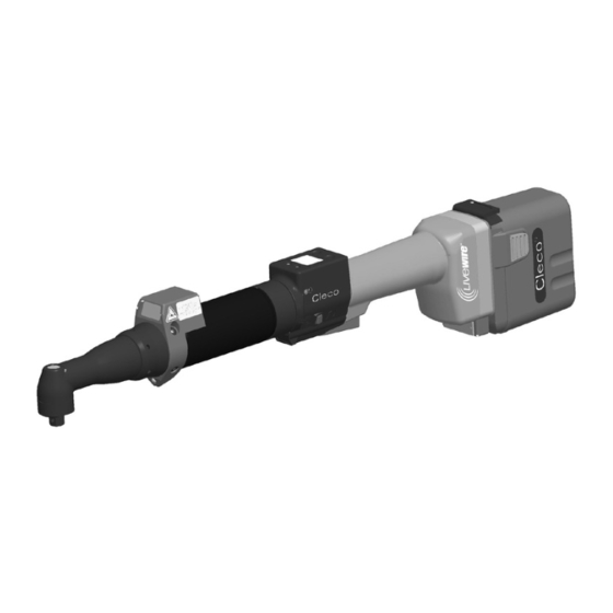
Product description Operation and functional elements This chapter describes the operating and functional elements and their functions: Fig. 3-1: Function keys LED display Start button Reverse switch IrDA (infrared interface port) Set torque – stick-on marking foil LED lights for fast location of the fastening position Rechargeable Battery LCD display with information on torque, angle and status P1840E/EN 02/06... -
Page 11: Function Keys
Product description 3.2.1 Function keys Left function key • Confirm error message Press once. • Activate Diagnosis menu e.g. query number of rundowns to complete the service schedule. Press for three seconds: Test Menu. Press once. Count. To exit the menu, press this key for three seconds: Exit Menu. Right function key •... -
Page 12: Start Button
Product description 3.2.3 Start button The start button has 2 functions (Standard for TMEB-100): • It activates the LED lighting. Press down the button halfway and hold it. • It starts the motor, the LED lighting goes out. Hold down the button completely. 3.2.4 Reverse switch The reverse switch changes the rotation direction of the 47BA:... -
Page 13: Identification - Set Torque
Product description 3.2.7 Identification – set torque To identify the set torque on the 47BA, glue the corresponding marking foil to the right and the left of the LCD display. Part no. 935330 3.2.8 LED lighting LED lighting make it possible to quickly find the screw point. To start it, press the start button half way (see 3.2.3 Start button, Seite 12). -
Page 14: System Overview - Optional Accessories
Product description System overview – optional accessories 47BA – Communication unit – (Scope of supply) Alternative: Controller for Controller with electric nutrunner PC software TMEB-100 TMEB-COM RS232 Tool holder with IrDA interface port and RS232 connection cable Part no. 935290 Replacement battery Part no. -
Page 15: Before Initial Operation
Before initial operation Before initial operation The 47BA has been configured by Cooper Power Tools. A setting for your specific screw joint needs must only be made with the TMEB-100 controller or a PC by a qualified person. See the following: •... -
Page 16: Replacing The Battery
Before initial operation Protect the battery from impact. Keep the charger and battery contacts clean and dry. Protect the battery from moisture. The battery can remain in the charger when not in use. Power is supplied to it via a float charge. Replace used batteries and recycle them (see 10 Environment, page 28.) Replacing the battery Inserting the battery... -
Page 17: First Operation
First Operation First Operation Perform the rundown Make sure that the battery is securely installed before operating the 47BA. The 47BA is now ready for use. After you press and release the start lever, the LCD display shows the message Ready. When the rundown has been done, place the tool into the tool holder. - Page 18 First Operation P1840E/EN 02/06 40b_1_5 en.fm, 12.04.2006...
-
Page 19: Lcd Display
LCD display LCD display Results display Die LCD display consists of a three-line display with 6 characters each to indicate status, torque and angle. First line – Status: Result is OK Result is not OK Torque transducer offset fault Torque transducer calibration fault Angle encoder fault Current overload in output section Requested motor output is too high... -
Page 20: Status
LCD display Status RUN Screen Ready Ready is displayed when no other status message takes precedence and the tool is ready for operation. Standard operating mode Remain Standard mode is selected when Linking is not activated. The application is selected at the Run Screen or via the App. -
Page 21: Set Position (Only Allowed With Linking)
LCD display Set position (only allowed with Linking) Activate Set position Hold 3 sec. To activate the Set position menu, you must hold down the right-hand button for three seconds. NOTE Set position can only be enabled if TMEB-100 is activated in the Advanced application builder\System settings\Set tool enable position menu. -
Page 22: Communications
LCD display Deactivate Set position Hold 3 sec. To deactivate the Set position menu, you must hold down the right-hand button for three sec- onds. Leave menu After three seconds, the message Leave Menu is displayed and you can release the right-hand button. - Page 23 LCD display Linkin Result No Linking result; Linking was terminated without an overall result. Not all of the positions in the tightening group have been programmed. Check the selected appli- cation or tightening group at the TMEB-100 to see if tool settings and process programming have been performed.
-
Page 24: Diagnostics
LCD display Sync Error Error during last synchronization of data with the TMEB-100; the tool must be synchronized with the TMEB-100 again. Tool Init Tool has not yet been synchronized with a TMEB-100; the tool must be synchronized with the TMEB-100 for the first time. Input Enable Missin... - Page 25 LCD display Diag locked If diagnosis is not enabled, the message Diagnosis Disabled is displayed. Test menu After three seconds, the message Test Menu is displayed and you can release the left-hand but- ton. The first Test Function (display tool system time) is then shown. NOTE While test functions are active, fastening cannot take place, or only the test function parameters can be used.
- Page 26 LCD display Display Counter Display Counte 999999 The tool counter display is incremented after each rundown throughout the service life of the tool. You can also view the counter display on the TMEB-100 under Diagnosis\Tool\Tool Memory. Display calibration test Cal OK K 1.11 O 0.00 This test function cyclically recalibrates the system with the values used immediately before the...
- Page 27 LCD display Monitoring criteria are the torque and a monitoring time. If the torque exceeds 15 % of its calibration value (even during the dwell time), or if the monitor- ing time of 4 seconds expires, the test run is terminated with a TQ> or TMAX result. The user must check, if the output shaft has actually turned by the value indicated (e.
- Page 28 LCD display Activate Emergency NOTE The emergency function can only be activated if it is activated in the TMEB-100 in the Advanced application builder\System settings\Enable emergency function menu. Emerge Strate locked Emergency function is disabled. Emerge Strate If activated in the TMEB-100 in the Advanced application builder\System settings\Enable emer- gency function menu, the emergency function can be enabled and disabled in the Diagno- sis\Emergency function menu with the tool start button.
-
Page 29: System Fault Messages
LCD display System fault messages NOTE If a fault is displayed, fastening is disabled until the fault is acknowledged with the left-hand but- ton on the tool. In the event of serious hardware faults, the tool is not enabled again even after the fault is acknowledged, and must be returned to the manufacturer for repair. - Page 30 LCD display Servo Error The current setpoint has been exceeded. Remedy: there may be a short-circuit. Return tool to manufacturer for repair. Servo Error Temp > The Servo has overheated. Remedy: Switch the tool off for a time so that it can cool down. Increase the cycle time, reduce the fastening time or the torque.
- Page 31 LCD display Servo Error Angle Tool angle encoder is sending incorrect signals to the Servo amplifier. Remedy: Return tool to manufacturer for repair. voltag warnin Warns that battery is running low. Remedy: Recharge battery or replace it with one that is already charged. Tool Error Counte...
- Page 32 LCD display Transd Error Transducer calibration voltage fault. Remedy: Tool was not relaxed at time of calibration. Allow tool to relax and try again. If this does not help, return to tool to the manufacturer for repair. Transd Error Transducer offset voltage fault. Remedy: Tool was not relaxed at time of calibration.
-
Page 33: Maintenance
Maintenance Maintenance Service schedule Regular maintenance reduces operating faults, repair costs and downtime. CAUTION! Danger of injury due to unintentional activation – before service - disconnect the 47BA from the battery. After... fastening cycles Actions 100,000 Check housing components for damage Check to ensure battery contacts are clean Check to ensure battery charger is clean 250,000 or once a year... -
Page 34: Lubrication Products
Maintenance Lubrication Products For smooth function and a long service life, use of the correct grease types according to the table is essential. Grease lubricants according to DIN51502 /ISO3498 Part no. Pack. Standard unit designation [ kg ] DIN / ISO Special Aralub Energrease... -
Page 35: Disassembling Angle Attachment
Maintenance Disassembling angle attachment Index, see 8 Spare parts, page 39 / 8.4 Fixture order list, page 46 P1840E/EN 02/06 40d_Wartung en.fm, 12.04.2006... -
Page 36: Assembling Angle Attachment
Maintenance Assembling angle attachment P1840E/EN 02/06 40d_Wartung en.fm, 12.04.2006... - Page 37 Maintenance P1840E/EN 02/06 40d_Wartung en.fm, 12.04.2006...
- Page 38 Maintenance P1840E/EN 02/06 40d_Wartung en.fm, 12.04.2006...
-
Page 39: Spare Parts
Spare parts Spare parts Note Use only original CLECO spare parts. Failure to comply can result in reduced power and increased service requirements. If spare parts not manufactured by us are installed, the tool manufacturer is entitled to deny any warranty claims. We would be pleased to prepare a special offer for spare parts and wear parts. -
Page 40: Gear + Angle Attachment
Spare parts Gear + angle attachment Type 6 (3×) 10 (3×) 47BA15AM3 935263 541899 541894 542233 541897 542099 47BA21AM3 935262 – 541893 542231 541894 542079 47BA28AM3 935261 – 541893 542232 541897 542099 7.2 Lubrication Products , page 34 P1840E/EN 02/06 40e_Ersatzteile en.fm, 12.04.2006... - Page 41 Spare parts Index Benennung Description 25,98X0,94 Sicherungsring circlip 800116 Scheibe washer 541887 O-Ring o-ring 28,24X 0,78 542724 Zahnkranz toothed ring 542722 Steckritzel pinion gear Planetenrad idler gear 923095 Nadelkranz needle rim 3,X5,X 7, Planetenradträger gear cage Zylinderstift cylinder pin 541888 Planetenrad idler gear Nadelkranz...
-
Page 42: Angle Attachment
Spare parts Angle attachment Always replace <29> and <31> as a set Calculation of the correct thickness of the shim ring (40) for adjustment of the bevel gear , page 45 8.4 Fixture order list , page 46 7.2 Lubrication Products , page 34 P1840E/EN 02/06 40e_Ersatzteile en.fm, 12.04.2006... - Page 43 Spare parts Index Benennung Description O-Ring o-ring 1011732 Halbschalensatz split-ring set 207309 Überwurfmutter union nut 935338 O-Ring o-ring 7,65X1,78 504970 934023 Gewindering threaded ring 934035 Rillenkugellager ball bearing 10,X 22,X 6, Hülse sleeve 934021 12,7 X Nadellager needle bearing 19,05X12,7 934027 Kegelradsatz bevel gear set...
-
Page 44: Tool Holder With Irda Interface Port
Spare parts Tool holder with IrDA interface port P1840E/EN 02/06 40e_Ersatzteile en.fm, 12.04.2006... - Page 45 Spare parts Index Benennung Description Abdeckkappe 40,X40, S900983 Nutenstein slot nut S900418 Strebe brace 935292 Schrauberauflage support 935293 935294 Auflage support Bundbuchse plug 935291 Zylinderschraube cap screw M 8X 65 902490 Verschluss locking cover 935303 IrDA-Serial Adapter IrDA-Serial Adapter 935170 917735 Spannstift dowel pin...
-
Page 46: Fixture Order List
Spare parts Fixture order list Index Part no. Name 933450 Reassembly equipment 933451 Punch 933453 Base 933452 Punch 933454 Reassembly equipment 933455 Punch 933456 Base 933449 Reassembly equipment 933457 Punch 933458 Base 933448 Equipment Disassembly 900009 Cap screw 933459 Thrust pad 933460 Sleeve 933461... -
Page 47: Service
Service Note If repair is required send the complete 47BA to Cooper Power Tools. A repair is only permitted by Cooper Power Tools authorized personnel. If the tool is opened, the warranty is voided. Contact person for all customer service and repair services: Mr. -
Page 48: Technical Data
Technical Data Technical Data 10.1 Dimensions 47BA Fig. 10-1: Dimensions of 47BA (mm) P1840E/EN 02/06 40f_Service en.fm, 12.04.2006... -
Page 49: Dimensions Of Tool Holder (Optional)
Technical Data 10.1.1 Dimensions of tool holder (Optional) Fig. 10-2: Dimensions of tool holder (mm) 10.2 Performance Data Type Recommended torque Free Screw Weight Calibration data range speed size without with Torque Angle pulses Recharge- Recharge- (nominal) (Resolver) able Battery able Battery ¹/min ¹... -
Page 50: Electrical Data
Technical Data 10.3 Electrical data Tool Protection class III as per DIN EN 61140 (VDE 0140-1) Degree of protection IP40 as per DIN EN 60529 (IEC 60529) Tool holder Protection class III as per DIN EN 61140 (VDE 0140-1) Degree of protection IP40 as per DIN EN 60529 (IEC 60529) 10.3.1 Battery power supply Battery type... -
Page 51: Irda Interface Port
Technical Data 10.3.4 IrDA interface port Supply voltage 5.0 V (4.8 to 5.5 V) Power consumption 0.30 VA Maximum current 11 mA Transmission speed: 57.6 kbit/s Parity Bit none Data Bit 8 bit Stop Bit 1 bit Error check 10.3.5 WLAN interface port Description Data... -
Page 52: Disposal
Battery ordinance (BattV) the tool and the nickel metal hydride battery must be recycled in an environmentally friendly manner. Return the tool and defective/used batteries to your company collection facility or to Cooper Power Tools. Do not throw the battery in household refuse or in water. Do not open the battery. P1891E/EN 11/06... -
Page 53: Glossary
Glossary Glossary Angle Angle that is to be reached at the end of the fastening sequence (also final angle, rated angle, or nominal angle). Angle High Limit [AHL] Maximum admissible angle of rotation for a fastening stage. Application Programmed setting of the tool for a specific fastening sequence of up to 6 stages. - Page 54 Glossary Torque transducer Sensor for measuring torque. Turn off angle Angle at which a tool is shutoff Turn off torque Torque at which a tool is shutoff P1840E/EN 02/06 40g_Glossar en.fm, 12.04.2006...
- Page 56 Cooper Power Tools Cooper Power Tools GmbH & Co. P.O. Box 1410 Postfach 30 Lexington, SC 29071-1410 D-73461 Westhausen Germany Phone: 803-359-1200 Tel: (49)7363-810 Fax: 803-808-6735 Fax: (49)7363-81222 www.cooperpowertools.com...
Need help?
Do you have a question about the Cleco 47BA B Series and is the answer not in the manual?
Questions and answers