Table of Contents
Advertisement
Quick Links
Advertisement
Table of Contents

Related Manuals for BACA SYSTEMS Miter X

Summary of Contents for BACA SYSTEMS Miter X
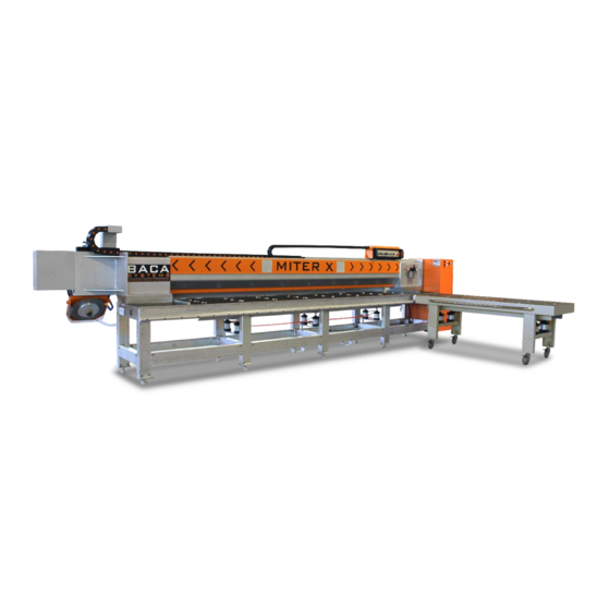
- Page 1 BACA Miter X Miter machine Operation Manual V1.05 Revised 03/16/2021...
-
Page 2: Table Of Contents
Contents Safety ................................3 Operation ..............................5 Preparation ............................... 5 StartUp ..............................6 Standard Operation ..........................6 Maintenance ............................. 8 Troubleshooting ............................9 Electrical ..............................9 Control ..............................10 V1.05 Revised 03/16/2021... -
Page 3: Safety
Applicable plant general safety practices must also be followed. BACA Systems designed your Miter X with safety in mind. Throughout this manual, safety precautions and warnings are highlighted for specific operations. Safety precautions are also posted on the equipment. - Page 4 Proper LOCKOUT/TAGOUT procedures must always be followed when servicing and/or maintaining the Miter X. Be aware that live electrical circuits are present in the control cabinet whenever the master disconnect is ON, regardless of whether the estop button is pressed or released.
-
Page 5: Operation
Operation Preparation Connect 220V 3P 60Hz to main disconnect through the cord grip. Tigthen the cord grip to ensure the cable doesn’t move. (Figure 1.1.1) Remove zip ties on Cat-Track and red shipping brackets. Connect minimum of 80PSI air connection to the regulator. Make sure the regulator is set to 80PSI to 0.5 Mpa. -
Page 6: Startup
StartUp Turn on the power disconnect and wait until the blue light illuminate. (Figure 1.2.1) Once the blue light illuminate, it means the power is turned on. (Figure 1.2.1) Wait for red blinking on saw stop and carriage stop button. This red blinking means that the PLC is ready to be operated. - Page 7 o Water valve ▪ Turn on the water valve o E-Stop ▪ Stop the saw movement, cutting unit movement, raise of the roller and the lowered of the clamp. Figure 1.3.1 Figure 1.3.2 represent the analog display for saw information and saw speed adjustment.
-
Page 8: Maintenance
Clamps and rollers need to be disengaged or OFF. o Place larger pieces to be mitered on the Miter X table and now engage the rollers. The pieces will now be off the table and moving the stone into position will be easier. -
Page 9: Troubleshooting
Troubleshooting Electrical All Power does not turn on. o Turn on the Power Disconnect Switch and check if 220V is established using a multimeter o Check if all the Circuit Breakers work fine with 220V IN and OUT Carriage VFD power does not turn on o Check the Circuit Breaker CB153 and its Inputs 1L1 to 1L3 and Outputs 1530L1 to 1530L2 using a multimeter o Check the lines TB103-1U (24VDC) and TB103-2U (0VDC) -
Page 10: Control
Control Saw motor is not turning on o Try resetting the machine with the Reset Push Button on the Panel o Enable the Web Access for the PLC200 as shown in the MiterX Service Manual o Check for Input/Output issues in the “InputOutput_Status” and “SawVFD_CyclicStatus”...
Need help?
Do you have a question about the Miter X and is the answer not in the manual?
Questions and answers