Table of Contents
Advertisement
Advertisement
Table of Contents

Related Manuals for Valmet Flowrox FXM Series

Summary of Contents for Valmet Flowrox FXM Series
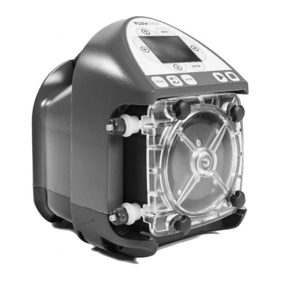
- Page 1 Installation, operation and maintenance instructions for Flowrox™ FXM peristaltic metering tube pumps Installation, maintenance and operating instructions These instructions must be read carefully and understood prior to the installation, use, and servicing of this product.
- Page 2 NOT TRANSFERRED FROM VALMET TO ANYONE IN CONNECTION WITH THIS MANUAL. THIS MANUAL IS INTENDED TO BE USED ONLY BY VALMET´ CUSTOMER AND EXCLUSIVELY FOR THE PURPOSES OF THE AGREEMENT UNDER WHICH THIS MANUAL IS DELIVERED TO VALMET´ CUSTOMER. WITHOUT THE PRIOR...
-
Page 3: Table Of Contents
Table of Contents 1 EU DECLARATION OF APPENDICES CONFORMITY Warranty Introduction Available Models Specifications Materials of construction Features Agency Listings 2 Installation Mounting Location 2.2 Dimensions 2.3 Installing Suction Strainer 2.4 Input Power Connections 2.5 WIRING TERMINALS AND I/O SCHEMATICS 3 How To Operate FXM Menu Navigation 3.2 Configuration Menu... -
Page 4: Eu Declaration Of Conformity
Low Voltage Directive 2014/35/EU Follow the pump installation, operating and maintenance instructions in this manual. Person authorised to compile the technical file is Technology Manager Jarmo Partanen. On behalf of Valmet Flow Control Oy In Lappeenranta, 13th May 2022 Riku Salojärvi... -
Page 5: Introduction
Introduction Congratulations on purchasing the Flowrox variable speed Peristaltic Metering Pump. Your Flowrox pump is pre-configured for the tubing that shipped with your metering pump. Your new pump has been pressure tested at the factory with clean water before shipping. You may notice trace amounts of clean water in the pre-installed tube assembly. - Page 6 Feed rate FXM2 Model Numbers Speed Pressure FXM3 Tube Pumps Norprene® Meets FDA criteria for food | Excellent chemical resistance | CIP | SIP liter/h ml/min 115V AC (US) 230V AC (US) 230V AC (EU) 230V AC (UK) 230V AC (AUS) (gal/h) (oz/min) (psi)
-
Page 7: Specifications
1.3 Specifications Maximum working pressure (excluding pump tubes): Motor speed adjustment range 5.000:1: FXM2: 8.6 bar / 125 psi 0.02% - 100% motor speed FMX3: 4.5 bar / 65 psi Note: see individual pump tube assembly maximum pressure Motor speed adjustment resolution: ratings in Section 1.2 (Available Models) 0.1% increments >... -
Page 8: Materials Of Construction
1.4 Materials of construction Mounting plate: Wetted components: Stainless steel AISI 316 Pump Tube Assembly (Model Specific - 2 provided): Tubing: ... . Norprene or Tygon lined Norprene or Tygothane ... -
Page 9: Agency Listings
Enclosure Rating: Symbol Explanation NEMA 4X: Constructed for either indoor or outdoor use to provide a degree of protection to personnel against incidental Risk to personal safety: Neglecting the safety measures can cause serious injury contact with enclosed equipment; to provide a degree of or death. -
Page 10: Installation
Installation Risk of chemical overdose. Make sure pump does not overdose chemical during backwash and periods of no flow in circulation system. Always wear protective clothing, face shield, safety glasses and gloves when working on or near your metering pump. Additional precautions should be taken depending on solution being pumped. -
Page 11: Dimensions
2.2 Dimensions Dimensions in mm (inches in parenthesis) FXM2: FXM3: 4FXM70EN - 8/2022... -
Page 12: Installing Suction Strainer
2.3 Installing Suction Strainer 2.4 Input Power Connections WARNING! Proper eye and skin protection must be worn when Electrocution hazard. installing and servicing pump. Cord connected models are supplied with a grounding conductor and grounding-type attachment plug. To reduce risk of electric shock, be certain that it is connected only to a properly grounded, grounding-type receptacle. - Page 13 TERMINATION BOX COVER POWER CORD OPTIONS Cable and conduit connectors included QTY. DESCRIPTION M20 CABLE GLAND, ACCEPTABLE CABLE DIAMETER FROM 7 TO 13 MM POWER CORD CONNECTOR PWF-03PMMS-SC7001 ETHERNET CONNECTOR RJ45 PROFIBUS CONNECTOR (IN FUTURE OPTION) 4FXM70EN - 8/2022...
-
Page 14: Wiring Terminals And I/Oschematics
2.5 WIRING TERMINALS AND I/O SCHEMATICS Connector box layout 4FXM70EN - 8/2022... - Page 15 FUNCTION TERMINAL PIN# PIN NAME RATING ELECTRICAL SP. 4-20mA input (+) positive 120 Ohm impedance, Input: 4-20 mA non-powered loop (-) negative Pulse (+) positive high: 2 to 30 VDC Input: Pulse low: < 0,7 VDC (-) negative Rising edge triggered (+) positive Input: Frequency input...
-
Page 16: How To Operate Fxm
How To Operate FXM FXM Control Panel – Button Operation A sample of pump displays showing items on main display. 4FXM70EN - 8/2022... -
Page 17: Menu Navigation
Sample screen shots Menu Navigation Use MENU button to enter menu for setting up pump. Use UP or DOWN arrows to navigate through menu. Active option appears on pump display in inverse text. Arrow symbol signifies top of a menu tree. This means you can go further within menu. -
Page 18: Configuration Menu
3.2 Configuration Menu Below is menu structure for Configuration screens. 4FXM70EN - 8/2022... - Page 19 Language Selection Press MENU button to enter menu structure for setting up pump. Select Configuration and Press ENTER button. Select Display Language and Press ENTER button. Select your desired language, then Press ENTER. Select OK at bottom of list to confirm your selection. Press ENTER button.
- Page 20 Capacitance calibration Tube Leak Detection (TLD) operation is based on capacity measurement at pump head. Once the ambient (base) capacitance is set by the calibration feature, that value is the 0 point in the scale and then there is a 1-40 trigger level setting that spreads the sensing range across those settings.
- Page 21 Select ←Back on following screens to move back up to desired menu location. NOTE: For features in Set Diagnostics Username and Diagnostics Use, please contact Valmet Flow Control Oy Display Rate (Units of Measure) By default, pump will display %Speed (motor speed) and RPM.
- Page 22 Switch Direction Reset Factory Defaults This will switch pump rotation direction. This will reset pump to factory defaults. This will restore pump to original configuration when it left the factory. Press MENU button to enter menu structure for setting up pump.
-
Page 23: Input Setup
4 Input Setup Below is the menu structure for the INPUT SETUP selection. 4FXM70EN - 8/2022... - Page 24 4FXM70EN - 8/2022...
-
Page 25: Max Flowrate (Output Calibration)
• When the piping system configuration is changed. MAX Flowrate (output calibration) • When the suction lift height is changed. The MAX Flowrate value is equal to the pump’s measured • Periodically during the life of the tube. Output variances fluid output in millilitre per minute, at the 100% motor speed are most noticeable prior to tube failure. - Page 26 you pass your desired digit, you can easily scroll back by Manual Adjust (manual speed adjust) continuously pressing RIGHT button. Used to manually control speed of pump. Use up and down Press ENTER to save changes. arrows to adjust the speed while the pump is running or set % Continue this process until all four screens have been (percent) Motor Speed in this menu.
- Page 27 0 – 10 VDC Input (Volt DC) Used to remotely control pump with an incoming 0-10 VDC signal. Default settings: 0 VDC = 0% motor speed 10 VDC = 100% motor speed Press SELECT RUN MODE button until 0 – 10 VDC Input is displayed in the top line of the display.
- Page 28 Frequency Input (Hz) Pulse Batch Input (low speed pulse) Used to remotely control pump with an incoming high speed Used to remotely control pump with an incoming pulse frequency signal. Typically used with flow meters or other signal. Can be used with an external foot pedal, a water meter, external devices.
- Page 29 Manual Cycle Adjust (repeating cycle timer) Used to run at a pre-selected motor speed for a specified run time. This cycle will repeat itself using a repeating cycle timer. Default settings: 100% motor speed for 1.5 seconds Repeating cycle timer = 4 seconds Press SELECT RUN MODE button until Manual Cycle Graphical representation of Manual Cycle Adjust injection Adjust is displayed in the top line of the display.
- Page 30 Dispensing Manual Dosing Configure any dispensing amount or sample size and pump Used to configure Parts Per Million dosing to a system. will repeat it on command by pressing START button. Great This method can be used if treated fluid volume is a fixed for accurate single shot dispensing of a pre-configured amount (in Liters Per Minute).
- Page 31 To configure the pump, navigate to Proportional Dosing menu by pressing MENU button, then selecting Input Setup, Input Modes, and then Proportional. Press UP or DOWN arrow to scroll through 0 – 9 on selected digit. Press RIGHT arrow to scroll over to next digit to right. If you pass your desired digit, you can easily scroll back by continuously pressing RIGHT button.
-
Page 32: Contact Input
When Contact Input is enabled, the word Remote will be displayed on lower left side of screen at all times *NOTE: YOU MUST SET THE “CC1 OR CC2” FORMAT UNDER THE CONDITIONAL LOGIC SECTION 4.5 TO ENABLE INPUT CONTROL. Signal stopped pump: 4.2 Contact Input Used to remotely start and stop pump using a close=stop or open=stop signal. -
Page 33: Conditional Contact Input Naming
4.5 Conditional Logic Control • Conditional Contact Inputs can be used to operate the pump in much the same way as a simple program controller. • All other alarm conditions must be satisfactory before these functions can run. • AND statements are related to two inputs that must be satisfied for the pump to be allowed to run. -
Page 34: Output Setup ( Alarm Relays )
Output setup ( alarm relays ) Contact #1 shown only. Contact #2, and Contact #3 use the same menu items. Below is menu structure for Output Setup screens. 4FXM70EN - 8/2022... -
Page 35: Signal Output
Description of Relay and Contact Closure Output triggers Continue this process until all four screens have been Selection Contact energizes when configured. Pump Run/Stop Motor turning (roller assembly is rotating). Incoming analog or digital signal is not received or is Monitor Input To navigate back out of menu structure you must select ←OK out of range. -
Page 36: Pump Maintenance
6 Pump Maintenance Disconnect power from the pump. Carefully purge any pressure in the discharge line of the pump. Disconnect the suction end tubing/piping and the discharge end tubing/ Always wear protective clothing, face shield, safety piping from the pump head tubing. glasses and gloves when working on or near your metering pump. -
Page 37: Tube Replacement
In this mode, the pump rotor can rotate up to 6 revolutions 6.4 Tube Replacement per minute for your safety. Prior to service, pump clean water through the pump and suction / discharge line to remove chemical. Always wear protective clothing, face shield, safety glasses and gloves when working on or near your metering pump. - Page 38 Locate your new tubing. Please see below on how to install new Tube Assembly into Pump Head. Continue to follow rotation of rotor while directing tube into pump head. At this point, you may need to pull the tube to Insert suction fitting into pump head.
- Page 39 Re-attach Pump Head Cover using the four Thumb Screws. Pump will detect Pump Head Cover is installed and begin to exit MAINTENANCE MODE. Pump will ask you if Tube was replaced. Yes / No If Yes is selected, pump ask you to reset Tube Timer. Yes / No If Yes is selected, pump will display Current Tube Timer briefly (5 seconds) before resetting to zero.
-
Page 40: Flowrox Model Fxm2 Replacement Parts List
6.5 FLOWROX Model FXM2 replacement parts list FXM2 Replacement Parts List Item Description Flowrox Description Item code Pump Head FXM2-TP-PH 112881 Plunger Assembly FXM2-TP-PA Q86422 Roller Assembly (Rotor), For N011, (ND) Tubes : GROUP 1 FXM2-S-G1-R Q86411 Tubing in this group are interchangeable with single Tube Assembly, 3/8"... - Page 41 * ONLY WITH 3/8" TUBE NUT CONNECTORS *5.1 4FXM70EN - 8/2022...
-
Page 42: Flowrox Model Fxm3 Replacement Parts List
6.6 FLOWROX Model FXM3 replacement parts list FXM3 Replacement Parts List Item Description Flowrox Description Item number Pump Head FXM3-TP-PH 112885 Plunger Assembly FXM3-TP-PA Q8646 Roller Assembly (Rotor), For N151, , (NH, NK,) Tubes : GROUP 1 FXM3-S-G1-R Q86498 Tubing in this group are Tube Assembly, 1/2"... - Page 43 4FXM70EN - 8/2022...
- Page 44 The serial label must be on the pump and legible. The warranty status of the pump will be verified by Valmet Flow Control or a factory authorized service center.
- Page 45 4FXM70EN - 8/2022...
- Page 46 Subject to change without prior notice. Neles, Neles Easyflow, Jamesbury, Stonel, Valvcon and Flowrox, and certain other trademarks, are either registered trademarks or trademarks of Valmet Oyj or its subsidiaries in the United States and/or in other countries. For more information www.neles.com/trademarks...
Need help?
Do you have a question about the Flowrox FXM Series and is the answer not in the manual?
Questions and answers