Table of Contents
Advertisement
Quick Links
Advertisement
Table of Contents

Related Manuals for Coolmay C200H Series


Summary of Contents for Coolmay C200H Series
- Page 1 https://en.coolmay.com/...
- Page 2 C200H AC Servo Manual https://en.coolmay.com/...
- Page 3 Please ground the grounding terminal reliably. Poor grounding may cause electric shock or fire. Please do not connect 380V power supply to 220 V servo drives, otherwise it will cause equipment damage and electric shock or fire. https://en.coolmay.com/...
- Page 4 5. Maintenance and inspection Prohibition Do not touch the inside of the driver and its motor, otherwise it will cause electric shock. When the power is started, do not disassemble the driver panel, otherwise it https://en.coolmay.com/...
- Page 5 6. Scope of use Caution The products involved in this manual are for general industrial use. Do not use them on devices that may directly endanger personal safety. https://en.coolmay.com/...
-
Page 6: Table Of Contents
5.4 Origin Regression Function And Relevant Parameters Introduction..50 5.5 Pre-operational Inspection................52 Chapter 6 Operation And Display................54 6.1 Drive Panel Introduction................54 6.2 Main Menu....................55 6.3 Steps To Set Parameters................55 6.4 Status Monitoring..................56 6.5 Analog Quantity Zeroing Adjustment............58 https://en.coolmay.com/... - Page 7 6.7 How To Reset Default Parameters............. 59 Chapter 7 Parameters....................60 7.1 PA Group.....................60 7.2 P3 Group Parameters For Multifunctional Terminals........ 81 7.2.1 Parameter Table..................81 7.3 P4 Group Parameters For Internal Position Command......91 Chapter 8 Error Code....................98 Chapter 9 Alarm Handling Methods...............100 https://en.coolmay.com/...
-
Page 8: Chapter 1 Product Inspection And Installation
However, the servo motor with holding brake is unable to rotate directly. If there is any break down item or abnormal phenomenon mentioned above, please contact with the dealer immediately. If there is any discrepancy, please contact the purchasing agents. https://en.coolmay.com/... -
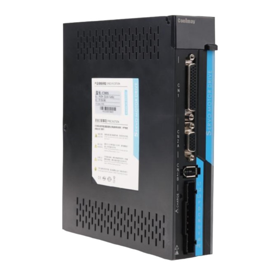
Page 9: Product Front Panel
Therefore, do not touch the power terminal when the lights on to avoid electric shock. P,D,C,N Regeneration resistance terminal ⑦ U,V,W Servo motor UVW connection terminal ⑧ Ground terminal ⑨ https://en.coolmay.com/... -
Page 10: Product Installation
Cooling The servo drive adopts natural cooling mode and forced heat dissipation mode. Installation considerations Prevent dust or iron chips from entering the servo drive when installing the electrical controlling cabinet. https://en.coolmay.com/... - Page 11 Places without corrosive and igniting gases, oil and gas, cutting fluid, cutting powder, iron powder, etc. No steam and avoid direct sunlight. Servo Motor Installation 1.3.3 For horizontal installation:In order to prevent water, oil, etc. from entering inside of the https://en.coolmay.com/...
- Page 12 The motor rotating direction description in this handbook is defined as facing the shaft of the servo motor, if the rotating shaft is in counterclockwise direction will be called as positive direction, or in clockwise as reversal direction. Pic1.4 Motor Rotation Direction https://en.coolmay.com/...
-
Page 13: Chapter 2 Servo Specifications
C200H AC Servo Manual Chapter 2 Servo Specifications 2.1 Servo Drive Specification Model C200H Power 1KW~3KW 1 phase/3 phases Main Circuit AC220V-15%~10% 50/60Hz 0: Position. 1: Speed. 2: Torque. 3: Position and speed. 4: Position and Control Mode torque. 5:Speed and torque Protection Over speed, Over voltage, Under voltage,Overload, Abnormal of main Function... -
Page 14: Servo Drive Naming Rule
② ③ ④ ⑤ Serial No. Definition ① Coolmay technology C series servo driver. Power: 100:0.05KW~1KW. 200:1KW~2KW. ② H: High performance and for 2500ppr incremental encoder or 17-bit ③ single/multi-turn absolute encoder. ④ The branch power range below 1KW: 40: 0.05KW~0.4KW; 75:0.4KW~0.75KW. -
Page 15: Servo Motor And Matched Servo Drive List
C200H AC Servo Manual Servo Motor And Matched Servo Drive List Table 2-1 Power Speed Matched Flange Model Encoder (RPM) Drive 80mm CN80-04025A6-MH(B) 1000 2500 90mm CN90-04025A6-MH(B) 1000 2500 CN130-04025A6-MH(B) 1000 2500 CN130-05025A6-MH(B) 1800 2500 CN130-06025A6-MH(B) 2500 CN130-07725A6-MH(B) 2500 17-bit single turn C200H absolute encoder CN130-10010A6-MH(B) -
Page 16: Chapter 3 Drive And Motor Dimension
C200H AC Servo Manual Chapter 3 Drive And Motor Dimension 3.1 Drive Dimension The user can install the servo drive with the bottom plate and the installed direction is perpendicular to the installation facing. Recommended to cool the servo drive with fan or natural cooling. 400W Pic 3.1 C200H Dimension... -
Page 17: Motor Dimension
C200H AC Servo Manual 3.2 Motor Dimension Flange 80mm,90mm ● Pic 3.2 Flange 80mm/90mm And Table 3-1 Model DM80-04025A1/A6-MA DM90-04025A1/A6-MA Flange 130mm ● Pic 3.3 Flange 130mm And Table 3-2... - Page 18 C200H AC Servo Manual Model CM130-04025A1/A6-MH CM130-05025A1/A6-MH CM130-06025A1/A6-MH CM130-07725A1/A6-MH CM130-10010A1/A6-MH CM130-10015A1/A6-MH CM130-10025A1/A6-MH CM130-15015A1/A6-MH CM130-15025A1/A6-MH...
-
Page 19: Chapter 4 Drive System Wiring And Introduction
C200H AC Servo Manual Chapter 4 Drive System Wiring And Introduction 4.1 Servo System Wiring 4.1.1 Servo Drive Wiring Pic 4.1 Servo System Wiring... - Page 20 C200H AC Servo Manual 4.1.2 Wiring Introduction Wiring Notes: Cable length, command cable within 3M, encoder length within 20m. Check whether the power supply and wiring of L1, L2 and L3 are correct. If only 220VAC drives are supported, do not connect to 380VAC power supply. The phase sequence of the motor output u, V and W terminals must correspond to the ...
-
Page 21: Servo Driver Terminals Introduction
C200H AC Servo Manual 4.2 Servo driver terminals Introduction Pic 4.2 C200H Drive Terminals The above picture shows the pins arrangement of the drive. -
Page 22: Main Circuit Terminal
C200H AC Servo Manual 4.3 Main Circuit Terminal 4.3.1 Main Circuit Terminal Introduction Pic 4.3 Main Circuit Terminal Terminal Name Symbol Detailed Explanation Connect to external AC power supply ,1 phase L1、L2 220VAC -15%~+10%,50/60Hz. Main Power Supply Connect to external AC power supply ,3 phases L1、L2、L3 220VAC -15%~+10%,50/60Hz. - Page 23 C200H AC Servo Manual 4.3.2 Regeneration Resistance Connection If use the built-in resistor, please connect P and D( a 4 pins connector for built-in resistor has been set by factory, so you can insert it to the terminal directly), as picture A showed. When an external regeneration resistance is connected to the servo drive, the short circuit between terminal P and D must be disconnected.
-
Page 24: Cn1 Control Signal Terminal
C200H AC Servo Manual CN1 Control Signal Terminal CN1 Terminal Introduction 4.4.1 The CN1 connector DB44 plug provides the signals interfaced with the host-controller. The signal includes: 8 programmable input terminals 6 programmable output terminals Analog command inputs ... - Page 25 C200H AC Servo Manual Pic 4.5 CN1 Terminal 4.4.3 Position Instruction Input Signal Signal Name Pin No. Function PULS+ High speed photo isolation input. Working mode is set by parameter PA14: PULS- Pulse+direction. SIGN+ CCW/CW pulse. Position A、B orthogonal pulse. Pulse SIGN- ...
- Page 26 C200H AC Servo Manual If the output pulse width of the upper device is less than the minimum pulse width, it will cause the drive to receive error pulses. The terminal between PULS+ and PULS-/SIGN+ and SIGN- only support ...
- Page 27 C200H AC Servo Manual Common Cathode Connection, for example: Siemens PLC. B)For external power supply: Case 1: To use internal resistance of the drive (recommended ). Common Anode Connection: Common Cathode Connection:...
- Page 28 C200H AC Servo Manual Case 2: To use external resistance of the drive. Common Anode Connection: Common Cathode Connection: How to calculate the value of resistanceR1: VCC-1.5 =10mA R1+240 Table 4-1 R1 Recommendation VCC Voltage Power 2.4KΩ 0.5W 1.5KΩ...
- Page 29 C200H AC Servo Manual 4.4.4 Digital Quantity Input And Output Signal Signal Name Pin No. Function Introduction servo enable alarm clearance CWdrive inhibition CCW drive Optocoupler input and function can be inhibition programmable.Defined by parameter P3 Forward external group( P3-0~P3-17). torque limit The input voltage of COM is both of Reverse external...
- Page 30 C200H AC Servo Manual communication negative end RS485 communication RS485 communication positive end positive end Internal Internal 0V Internal 5V power output and the max Power Internal 5V output current 200mA。 Output Internal Internal 0V Internal isolated 24V power output Power and the voltage range is 20V~28V E24V...
- Page 31 C200H AC Servo Manual A) For internal 24V power supply: B) For external 24V power supply: Note: Do not support PNP mixed with NPN input. ...
- Page 32 C200H AC Servo Manual Output Circuit Of Digital Quantity Diagram For DO1 as an example( the DO1~DO6 interface circuit is the same): 1) When the upper device is relay input: 2) When the upper device is optocoupler input: Be sure to connect a continuation diode when the upper device is a relay, ...
- Page 33 C200H AC Servo Manual 4.4.5 Analog instruction signal Signal Name Pin No. Function Analog AS+、AT+ instruction Analog velocity/torque input, range: -10V~+10V. AS-、AT- input AGND Pulse Instruction Input Interface Diagram Two input types: differential (recommended) and single-end. Speed and torque share one analog input at range from -10V to +10V with resistance approximately at 10 KΩ.
- Page 34 C200H AC Servo Manual 4.4.6 Motor Brake Connection The brake lock is the mechanism that prevents the servo motor shaft from moving when the servo drive is in non-enabled state, so that the motor keeps the position locked and the moving part of the machinery will not move because of itself or external force.
-
Page 35: Cn2 Encoder Signal Terminal
C200H AC Servo Manual CN2 Encoder Signal Terminal CN2A Terminal Introduction 4.5.1 The encoder signal connector CN2 connects with the incremental encoder. A 15 pins plug is used. The pin chart as followings: Pic 4.7 CN2A Incremental Encoder Signal Terminal 4.5.2 CN2A Terminal Signal Introduction Signal Name Pin No. - Page 36 C200H AC Servo Manual Connect with the shielded layer of the ecoder Shielded Ground Metal Cover cable CN2B Terminal Introduction 4.5.3 The encoder signal connector CN2B connects with the absolute encoder. A 6 pins plug is used. The pin chart as followings: Pic 4.8 CN2B Encoder Signal Terminal CN2B Terminal Signal Introduction 4.5.2...
-
Page 37: Cn3 And Cn4 Terminal Definition
C200H AC Servo Manual CN3 And CN4 Terminal Definition 4.6.1 Communication Terminal Wiring Diagram Pic 4.9 Communication Terminal Wiring 4.6.2 Communication port definition Through the CN3 and CN4 ports on the drive, the communication can be established between the drive and PC、 PLC and other drives. The CN3 and CN4 pins are defined as follows: Terminal Name Name... - Page 38 C200H AC Servo Manual It can connect PC or the upper controllers through a special serial port cable, and it is forbidden to plug with electric. It is recommended to use twisted pair or shielded wire, the length of the wire ...
- Page 39 C200H AC Servo Manual Pic 4.11 Parallel Cable Diagram Of Multi Drives Table 4-3 Connection Between Multi Drives Drive RJ45( A end) PLC(B end) Signal Name Pin No. Signal Name Pin No. RS485+ RS485+ RS485- RS485- Cover Cover PE(shielded layer) PE(shielded layer)...
-
Page 40: Anti-Jamming Countermeasures Of Power Wiring
C200H AC Servo Manual 4.7 Anti-jamming Countermeasures of Power Wiring To suppress interference, please take the following measures: Instruction input cable length should be less than 3 meters,and encoder cable should be less than 20 meters. Recommend grounding cable over 2.0 mm² ... - Page 41 C200H AC Servo Manual The cable of the outer box connection used for grounding should be more than 3.5 mm² of coarse wire, and braided copper cables are recommended. When using the noise filter, please observe the precautions described in the following ...
- Page 42 C200H AC Servo Manual The ground wire of the noise filter is separated from its output power cord. Pic 4.15 Diagram Of Separating Cables Between Ground And Output Line Of Noise Filter Noise filters need to use a thick cable as short as possible to ground separately, and do not ...
- Page 43 C200H AC Servo Manual Pic 4.17 Ground Connection Handling Of Noise Filter...
-
Page 44: Chapter 5 Running Mode And Controlling Wiring
C200H AC Servo Manual Chapter 5 Running Mode And Controlling Wiring According to the command mode and operation characteristics of a servo drive, it can be divided into three operation modes: position control operation mode, speed control operation mode and torque control operation mode. The position control mode usually determines the displacement of the movement by the ... -
Page 45: Position Control Mode
C200H AC Servo Manual 5.1 Position Control Mode 5.1.1 Position Mode Introduction Pic 5.1 Position Mode Diagram The main steps for position mode are as follows: 1) Correctly connect the main circuit and the power supply , as well as the motor power cable and encoder cable. - Page 46 C200H AC Servo Manual 5.1.2 Position Mode Wiring Pic 5.2 Position Mode Wiring The voltage of the internal 24V power supply ranges 20V~28V, and maximum operating current 100mA. If use a external 24V power supply, please connect the external 24V+ to pin16(COM) and the external 0V to pin43(E0V). A power supply for DO output should be prepared by customers.
- Page 47 C200H AC Servo Manual 5.1.3 Parameter Settings In Position Mode Gain And Smooth Filter Parameter Introduction Range Default Value Control mode Position Proportional Gain 1-1000 Position Command Smooth Filter PA19 0-1000×0.1ms PA100 Command Filter Selection Digital Input (DI) Parameter Introduction Range...
- Page 48 C200H AC Servo Manual Digital Output(DO) Parameter Introduction Range Default Value Range of positioning completion PA16 0-3000 pulses Position deviation limit PA17 0-30000×100 pulses 6000 Position deviation error PA18 CWL,CCWL prohibited mode PA83 Hysteresis for position completion PA84 0-32767 Range for approach positioning PA85 0-32767...
- Page 49 C200H AC Servo Manual P3-20 Digital Output DO1 function 0-99 P3-21 Digital Output DO2 function 0-99 P3-22 Digital Output DO3 function 0-99 P3-23 Digital Output DO4 function 0-99 P3-24 Digital Output DO5 function 0-99 P3-25 Digital Output DO6 function 0-99 Position Command Introduction Of Internal Position Pr Mode ...
- Page 50 C200H AC Servo Manual The state of POS0-2: 0: contact break (open) 1: contact close CTRG↑: the moment from open (0) to close (1) Max: the command pulses of the motor in one revolution Absolute position register is broadly applied. User can easily complete periodicity actions by the above table.
-
Page 51: Speed Control Mode Wiring
C200H AC Servo Manual 5.2 Speed Control Mode Wiring 5.2.1 Introduction Pic 5.3 Speed Control Mode The main steps to use the speed control mode are as follows: 1) correctly connect the servo main circuit and the power supply of the controller, as well as the motor cable and encoder cable. - Page 52 C200H AC Servo Manual 5.2.2 Speed Mode Wiring (三相) Pic5.4 Speed Mode Wiring...
- Page 53 C200H AC Servo Manual 5.2.3 Parameter Settings In Speed Mode Parameter Introduction Range Default Value Control Mode Speed Proportional Gain 5-2000Hz Speed Integral Constant 1-1000ms Internal And External Speed PA22 Instruction Selection Internal Speed 1 PA24 -6000-6000r/min Internal Speed 2 PA25 -6000-6000r/min Internal Speed 3...
-
Page 54: Torque Control Mode
C200H AC Servo Manual 5.3 Torque Control Mode 5.3.1 Introduction Pic 5.5 Torque Control Mode The main steps to use the speed control mode are as follows: Correctly connect the servo main circuit and the power supply of the controller, as well as the motor cable and encoder cable. - Page 55 C200H AC Servo Manual 5.3.2 Torque Mode Wiring Pic5.6 Torque Mode Wiring...
- Page 56 C200H AC Servo Manual 5.3.3 Parameter Settings In Torque Mode Parameter Introduction Range Default Value Control mode PA29 Gain of analog torque command Set by yourself Selection for internal and external PA32 torque command PA33 Direction of analog torque command Zero offset compensation of analog PA39 torque command...
-
Page 57: Origin Regression Function And Relevant Parameters Introduction
C200H AC Servo Manual 5.4 Origin Regression Function And Relevant Parameters Introduction 5.4.1 Relevant Parameter Settings Parameter Introduction Value Default Value Origin detector type or search direction P4-32 setting Set the model of short distance movement P4-33 to the origin P4-34 Origin trigger start mode P4-35... - Page 58 C200H AC Servo Manual Origin Regression Mode Introduction(Must be in internal position mode) 5.4.2 A. Origin trigger start mode(P4-34) The origin trigger start mode is divide into two kinds of origin regression function. One is automatic performing and another is contacting trigger. Details as below: P4-34=0: close origin regression function.
-
Page 59: Pre-Operational Inspection
C200H AC Servo Manual as the origin point reference. Then Z pulse of return search(P4-33=0) or do not return search(P4-33=1) can be set as the precise mechanical origin point. If do not use Z pulse as the mechanical origin point, the positive edge of ORGP can be also set as the mechanical origin point(P4-33=2). - Page 60 C200H AC Servo Manual servo motor shaft and its related accessories. After ensuring that the servo motor can work normally without load, connect the load to avoid unnecessary danger. Check and ensure before running: 1)There is no obvious damage to the appearance of the servo drive. 2)Wiring terminals are insulated.
-
Page 61: Chapter 6 Operation And Display
C200H AC Servo Manual Chapter 6 Operation And Display 6.1 Drive Panel Introduction 6.1.1 Front Panel The panel consists of 5 digital LED and 4 buttons including 、SET to display 、 、 all system status and set parameters. The operation is hierarchical. button indicates “back”... -
Page 62: Main Menu
C200H AC Servo Manual 6.2 Main Menu The first layer is the main menu and has 8 operating modes in total. Press button to change the operation mode. Then press SET button to enter into the second layer and executes a concrete operation. -
Page 63: Status Monitoring
C200H AC Servo Manual 6.4 Status Monitoring In the first layer,select “DP--” and press SET button to enter into monitoring mode. There are 23 displays in total. Users select the desired display mode with key, and then press SET button to enter into the specific states. Status Operation Example... - Page 64 C200H AC Servo Manual No.4 alarm...
-
Page 65: Analog Quantity Zeroing Adjustment
C200H AC Servo Manual Status Operation Example Definition Relay open Relay Uncharged Relay alarming Main circuit working normally Main circuit Uncharged Main circuit not enabled Main circuit alarming Line voltage normally Line voltage too low Line voltage alarming Absolute motor position876543210 Analog Quantity Zeroing Adjustment Using this function,the servo drive can check analog zero offset automatically and write the offset value into parameter PA39 or PA45. -
Page 66: How To Reset Default Parameters
C200H AC Servo Manual the operation is activate. After that, press the key to return to the upper menu. 6.7 How To Reset Default Parameters To recover default parameters when: The parameters are scrambled and the system can not work properly. ●... -
Page 67: Chapter 7 Parameters
C200H AC Servo Manual Chapter 7 Parameters 7.1 PA Group Default Name Function Rang Value 1. User code:315. Password 0-9999 2. Motor model code:385. Motor The parameter is read-only and can not be modified. Table 80-130 selection The driver automatically identifies the motor model. Software The software version can be read but can’t be modified. - Page 68 C200H AC Servo Manual Default Name Function Rang Value 0:Display motor speed. 1:Display the current position is 5-bit low. 2:Display the current position is 5-bit high. 3:Display position command. (command pulse accumulation) is 5-bit low. 4:Display position command. (command pulse accumulation) is 5-bit high. 5:Display position deviation is 5-bit low.
- Page 69 C200H AC Servo Manual Default Name Function Rang Value To set control method: 0: position control mode 1: speed control mode Control 2: torque control mode mode 3:position + speed control mode selection 4:position + torque control mode 5:speed + torque control mode 6:encoder zeroing mode 1.Set the proportional gain of speed loop.
- Page 70 C200H AC Servo Manual you need higher torque response frequency, it is recommended to increase the setting value. 1. To set the characters of speed detection filter. 2. The value is smaller, the cut-off frequency is lower and noise from the motor is smaller. If the load inertia is great, reducing the setting value is Speed recommended.
- Page 71 C200H AC Servo Manual 1.Set the electric gear ratio for position command pulse. 2.In position control mode,it is convenient to match all kinds of pulse source through set the parameter PA12 and PA13, which helps to reach ideal control resolution(angle/pulse). 3.
- Page 72 C200H AC Servo Manual Default Name Function Rang Value 1.Set the input mode of position command pulse. 2.To set one of 4 input modes: 0: Pulse+Direction. Input mode 1: CCW pulse/CW pulse. of position 2: phase A and phase B orthogonal input. command 3: Internal position input.
- Page 73 C200H AC Servo Manual Default Name Function Rang Value 1.To filter the instruction pulse with exponential acceleration and deceleration, and the value represents the time constant. 2.The filter does not lose input pulses, but would occur command delay . Position 3.The filter applies in command 0-1000×0.
- Page 74 C200H AC Servo Manual Default Name Function Rang Value In speed control mode, it sets the source of speed command. It means: 0: Analog Terminal AS+,AS- input analog speed command. 1:Internal speed command is decided by SP1 and SP2 of digital input(DI): DI Signal Speed Command Internal Speed1(PA24)
- Page 75 C200H AC Servo Manual Default Name Function Rang Value Internal 1.Set the internal speed 1. -6000- speed 2.In speed control mode(PA22=0), when SC1 and 6000 selection 1 SC2 are OFF, internal speed 1 is the speed command. r/min 1.Set the internal speed 2. Internal -6000- 2.In speed control mode(PA22=0), when SC1 is...
- Page 76 C200H AC Servo Manual 1.Set the proportion for input voltage of analog Gain of torque and the actual motor running torque. analog 10-100 2. The setting value unit is 0.1v/100%. quantity (0.1v/ 3. The default value is 30, corresponding to torque 100%) 3v/100%, while it means if the input voltage is 3V, it...
- Page 77 C200H AC Servo Manual 2:Analog torque command+internal torque command: DI Signal Torque Command TRQ2 TRQ1 Analog Torque Command Internal Torque2(PA65) Internal Torque3(PA66) Internal Torque4(PA67) Note: 0 means off ,1 means on. The input direction of analog Reverse the input polarity of analog torque. torque command 1.The setting value is the percentage of rated...
- Page 78 C200H AC Servo Manual 3.When the limit is valid, the actual torque limit is the Minimum value of max overload capacity ,internal CCW torque limit and external CCW torque limit. Set external torque limit of the motor CW direction. 1.The setting value is the percentage of rated torque, for example, it is set to 1 time of rated torque, the value is -100.
- Page 79 C200H AC Servo Manual combination with an external position loop. Default Name Function Rang Value S type acceleration It makes the motor start and stop working stably and sets a part of time of S type acceleration and 0-1000ms deceleration deceleration curve.
- Page 80 C200H AC Servo Manual Default Name Function Rang Value 1.It defines the delay time from the motor current cutting off to BRK=ON and BRK=OFF when the The setting motor rotates. 2.To avoid a damage to the brake, the parameter mechanical makes the motor slow down and then makes the 0-200×10ms brake when...
- Page 81 C200H AC Servo Manual Default Name Function Rang Value 1.To reverse the input terminals. For unreversed terminals, it is valid when the switch is closed, while it is invalid when the switch is open. For reversed terminals, it is invalid when the switch is closed, while it is valid when the switch is open.
- Page 82 C200H AC Servo Manual input of input terminal is better, but the response frequency terminal becomes slow. Effective Set to: command 0: the rising edge is effective. pulse edge 1:the falling edge is effective. Set to: Soft reset 0:Soft reset is invalid. 1:Soft reset is effective and the system will restart.
- Page 83 C200H AC Servo Manual MODBUS MODBUS communication address. 1-254 ID NO. MODBUS communic 48-1152 MODBUS communication baud rate. ×100 ation baud rate 0: 8, N, 2 (MODBUS, RTU) 1:8,E,1 (MODBUS, RTU) 2:8,O,1 (MODBUS, RTU) The parameter decide the communication protocol. MODBUS Value 8 represents the transmitted data is 8 bits;...
- Page 84 C200H AC Servo Manual Value Speed When the difference between the actual speed 0-1000 coincidence and the instruction speed is less than this r/min range setting, the UCO2N(speed coincidence) is ON, otherwise OFF. numerator of electronic gear Refers to parameter PA12. 0-32767 for position command pulse...
- Page 85 C200H AC Servo Manual and recharge. Then it is effective. 1.To filtering the input SIGN signal. 2.The default value is the max pulse input frequency: 500KHz(kpps) The value is bigger, the max input frequency is slower. SIGN signal 3.To filter the noise from the signal line in filter of order to avoid incorrect counting happening.
- Page 86 C200H AC Servo Manual 3. The comparator has hysteresis function set by PA86. 4. Use this function in case that in near positioning, the host controller is accepting the NEAR signal to carry on the preparation to the next step. In general, this parameter value should be bigger than PA16.
- Page 87 C200H AC Servo Manual ON, otherwise it is OFF. 2.The comparator has hysteresis function set by PA90. 3.It also has polarity setting function: PA91 PA89 Comparator >0 Torque without direction >0 Only detect positive speed <0 Only detect reversal speed 1.If the motor torque is bigger than PA91, the ATRQ( torque arrival) of digital output(DO) is ON, otherwise it is OFF.
-
Page 88: P3 Group Parameters For Multifunctional Terminals
7.2 P3 Group Parameters For Multifunctional Terminals 7.2.1 Parameter Table C200H series driver has 8 input terminals and 6 output terminals. The terminal input and output definition values can be changed through P3 group series parameters to complete various input and output definitions. (the default low level of input terminal is valid). - Page 89 C200H AC Servo Manual P3-30 Virtual Input Terminal Control The State Value Of Virtual Input P3-31 00000000-11111111 00000000 Terminal P3-32 Virtual Output Terminal Control The State Value Of Virtual Output P3-33 0000-1111 0000 Terminal P3-38 Virtual I/O Input DI1 Function 0-99 P3-39 Virtual I/O Input DI2 Function...
- Page 90 C200H AC Servo Manual 7.2.2 DI Function Explanation Input terminals( 8 input terminals are corresponding to the definitions of P3-0,P3-1,P3-2,P3-7). Value Symbol Function Explanation NULL Input state dose not effect system. Input terminal of servo enable. OFF: servo driver can not be enabled and serv omotor Servo Enable is not excited.
- Page 91 C200H AC Servo Manual 2.Use this function for protection of the mechanical traveling limit.The function is controlled by the parameter PA20. Pay attention to that the default value of PA20 neglects this function.Therefore needs to modify PA20 if need to use this function: (1):...
- Page 92 C200H AC Servo Manual 3:speed command is lower than the value of PA75 When any one of the above conditions is not satisfied, it will perform normal speed control. In speed or torque control mode, speed or torque command: CZERO Zero Command OFF:Normal command ON::Zero command...
- Page 93 C200H AC Servo Manual When PA11=0, Gear1 and Gear2 combinations are Electronic Gear GEAR1 used to select different numerator of gear ratio: GEAR2 OFF GEAR1 OFF: numerator 1(PA-12) GEAR2 OFF GEAR1 ON: numerator 2 (PA-77) Electronic Gear GEAR2 GEAR2 ON GEAR1 OFF: numerator 3(PA-78) GEAR2 ON GEAR1 ON: numerator 4(PA-79) Position In position control mode, the position deviation...
- Page 94 C200H AC Servo Manual The corresponding relationship of the internal position selection: Internal Position Position POS2 POS1 POS0 CTRG Parameter POS0 Command Command Selection0 P4-2 ↑ P4-3 P4-5 ↑ P4-6 P4-8 Internal Position ↑ P4-9 POS1 Command P4-11 Selection1 ↑ P4-12 P4-14 ↑...
- Page 95 C200H AC Servo Manual 7.2.3 DO Function Explanation Output terminals(6 input terminals corresponding definitions P3-20,P3-21,P3-22,P3-25). Value Symbol Function Explanation Always Valid Forced output ON. OFF :Main power supply is off, or alarm occurs; Servo Ready ON:Main power supply is normal, no alarm occurs OFF :alarm occurs.
- Page 96 C200H AC Servo Manual OFF : motor torque has not reached the limitation. Torque TRQL ON : motor torque has reached the limitation. Limitation Torque limitation is set byPA34,PA35,PA36 and PA37. In torque control mode: Speed OFF : motor speed has not reached the limitation. ON : motor speed has reached the limitation.
- Page 97 C200H AC Servo Manual Forced Valid 7.2.4 DI There are 5 parameters( P3-15, P3-16, P3-17,P3-18,P3-19) in group P3 and they can force DI valid. (1) Corresponding functions for P3-15 is represented by 8-bit binary: Number Bit7 Bit6 Bit5 Bit4 Bit3 Bit2 Bit1 Bit0...
-
Page 98: P4 Group Parameters For Internal Position Command
C200H AC Servo Manual 7.3 P4 Group Parameters For Internal Position Command Default Name Function Rang Value Internal position 0: absolute position instruction. P4-0 instruction 1: incremental position instruction. control mode 1. When the internal position command is completed or stops,the output internal position command completes (CMDOK) this DO signal after The digital the delay time set by P4-1. - Page 99 C200H AC Servo Manual The move speed of 0-5000 P4-4 Internal To set the move speed of internal position instruction 1. 1000 r/min position instruction 1 The number of position cycles To set the number of position cycles of the second -30000- P4-5 of internal...
- Page 100 C200H AC Servo Manual The move speed of To set the move speed of internal position 0-5000 P4-10 internal 1000 instruction 3. r/min position instruction 3 The number of position cycles To set the number of position cycles of the fourth -30000- P4-11 of internal...
- Page 101 C200H AC Servo Manual The move speed of To set the move speed of internal position 0-5000 P4-16 internal 1000 instruction 5. r/min position instruction 5 The number of position cycles To set the number of position cycles of the sixth -30000- P4-17 of internal...
- Page 102 C200H AC Servo Manual The move speed of 0-5000 P4-22 internal To set the move speed of internal position instruction 7. 1000 r/min position instruction 7 The number of position cycles To set the number of position cycles of the eighth -30000- P4-23 of internal...
- Page 103 C200H AC Servo Manual 0: Find the reference origin and return to search for the Z phase pulse as the mechanical origin. 1: Find the reference origin and keep forward for Set the mode of the Z phase pulse as the mechanical origin. short distance P4-33 2: Find the rising edge of the detector ORGP as the...
- Page 104 C200H AC Servo Manual The cycle number of origin -30000- P4-38 To set the cycle number of origin regression offset. regression 30000 offset(HOF1) 1: To set the pulse number of origin regression offset. The pulse 2: When the parameter function HOF1 and HOF2 are number of origin set to 0, the origin is defined as Z pulse or ORGP by the +/-max.
-
Page 105: Chapter 8 Error Code
C200H AC Servo Manual Chapter 8 Error Code Error Name Introduction Normal Over speed Motor speed over than the setting values. Main circuit over voltage The voltage of main circuit is too high. Main circuit under voltage The voltage of main circuit is too low. The value of position deviation counter is over than Position overshoot the setting value. - Page 106 C200H AC Servo Manual The current motor is inconsistent with the selected Need to switch motor model model of the drive. AC input under voltage AC input under voltage. Over voltage when main circuit Over voltage when main circuit in powering up. in powering up Encoder communication fault Driver and encoder are not connected.
-
Page 107: Chapter 9 Alarm Handling Methods
C200H AC Servo Manual Chapter 9 Alarm Handling Methods Alarm Running state Reason Processing method name Appears when 1. The control circuit board 1. Replace the servo driver. the control is faulty. 2. Replace the servo motor. power is 2. Encoder failure. turned on The input command pulse Correctly set the input... - Page 108 C200H AC Servo Manual Alarm Running state Reason Processing method name Appears when the control Circuit board failure. Replace the servo driver. power is turned on 1. The power supply Appears when voltage is too high. the main 2. The power supply Check the power supply.
- Page 109 C200H AC Servo Manual Alarm Running state Reason Processing method name 1. Circuit board failure. 2. The power fuse is damaged. Replace the servo driver. Appears when 3. Soft start circuit failure. the main 4. The rectifier is damaged. power is 1.
- Page 110 C200H AC Servo Manual Alarm Running state Reason Processing method name Appears when the control Circuit board failure. Replace the servo driver. power is turned on Turn on the main power supply and control line, 1. Encoder zero point 1. Readjust encoder zero input the pulse change.
- Page 111 C200H AC Servo Manual Running Alarm name Reason Processing method state Appears 1. Circuit board failure. 1. Reduce the temperature of Drive when the 2. The temperature of the the driver. overheating drive was driver is too high. 2. Replace the servo driver. running 1.
- Page 112 C200H AC Servo Manual Alarm Running Reason Processing method name state Appears when the control Circuit board failure. Replace the servo driver. power is turned on 1. The power supply 1. Check the drive. voltage is low. 2. Power on again. 2.
- Page 113 C200H AC Servo Manual Alarm Running Reason Processing method name state Appears when the control Circuit board failure. Replace the servo driver. power is turned on 1. Check the load. 2. Reduce the start and stop Operate in excess of the frequency.
- Page 114 C200H AC Servo Manual Running Alarm name Reason Processing method state The PA94 parameter value is set too large, Holding brake the control pulse is Reduce the parameter delay coming, and the value of pa94. Not open holding brake has not been opened.
- Page 115 C200H AC Servo Manual Running Alarm name Reason Processing method state 1. Z pulse does not exist and encoder is broken. 2.Poor cable or shielding. 1. Replace the encoder. Encoder Z 3.The shielding ground 2. Check the encoder pulse loss wire is not connected interface circuit.
- Page 116 C200H AC Servo Manual Running Alarm name Reason Processing method state Provincial type Parameter settings do not PA62 parameters Encoder match. correctly. alarm UVW signal instability, UVW signal is poor. Check the wiring. jumping Write the motor Data CRC The motor encoder has not parameters of the check error written data, which are all 0.
- Page 117 C200H AC Servo Manual Running Alarm name Reason Processing method state Encoder After the encoder communicatio communication is established, Connect the encoder cable n abnormality it is interrupted and and power on again.。 disconnected. Encoder The encoder gives an alarm battery when the battery voltage is voltage...
- Page 118 C200H AC Servo Manual Running Alarm name Reason Processing method state The single turn position offset Single lap value stored by the driver position value Power on again. exceeds the encoder error resolution. The encoder continuously Encoderreports reports CF domain errors and Reset the encoder.
- Page 119 C200H AC Servo Manual Version 22.51...
Need help?
Do you have a question about the C200H Series and is the answer not in the manual?
Questions and answers