Table of Contents
Advertisement
Quick Links
Preferred Utilities Mfg Corp
Preferred Instruments div.
31-35 South Street, Danbury CT 06810
203-743-6741
www.preferred-mfg.com
SDI-JC-23D2 rev 8-23-22
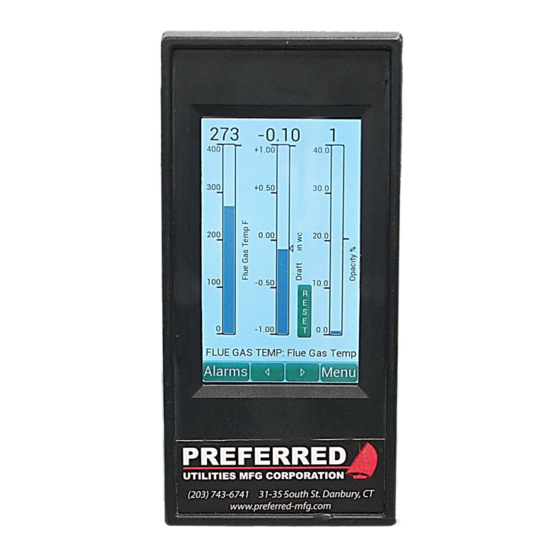
JC-23D2 Flue Temp, Opacity, Draft Controller
Installation & Operation Instructions
The JC-23D2 3-in-1 Flue Temp, Opacity and Draft controller maintains the
flue gas at a constant positive or negative Draft by modulating the outlet
damper on a boiler or furnace while also monitoring flue gas temperature
and stack opacity. A separate 4-20mA Draft transmitter is required to
modulate the damper.
The JC-23D2 interfaces to the burner flame safeguard to automatically
sequence the outlet damper Open for: Purge, Light-Off, and Post-Purge.
The sequence closes the damper after the burner shutdown to minimize
heat loss up the stack.
A separate time delayed Draft Cutout switch wired into the flame safeguard
Lockout Limits is required by Code for Safety.
.
The JC-22XMTR-xxCO includes a separate Draft xmtr and a separate time
delayed Draft Cutout switch in a single enclosure to reduce installation effort.
The JC-23D2 includes a burner shutdown relay that can be wired into the
FSG limits circuit for a high flue temp shutdown or a high opacity shutdown
or both.
Features
Automatic Draft Control for increased boiler efficiency and reliability.
Precision Outlet Draft Control for low NOx induced FGR burners.
Firing Rate Feedforward option is included and assures stable draft during
load changes. Separate curves for up to two fuels.
Automatic Damper Sequencing for purge, lightoff, post-purge burner
shutdown, and standby. Simple Flame Safeguard interface.
Damper Adjustable Start Position option is included for installations with
excessively high draft during lightoff.
High Flue Temp, Draft, and Opacity Alarms with time stamped alarm and
event history.
Light Source and Sensor 190851S and 190851D interface directly with
the JC-23D2.
Opacity Calibration is automated, there are no manual adjustments.
Automatic Opacity Calibration can be configured to occur when the burner
fan shuts off.
Flue Temperature Sensor accepts Type J or K thermocouple input.
5" Color LED Touchscreen for easy viewing. All setup can be done from
the touchscreen.
Modbus Communication with RS-485 and Ethernet capability.
NYC DEP Accepted
page 1 of 36
Advertisement
Table of Contents
Troubleshooting

Related Manuals for Preferred JC-23D2


Summary of Contents for Preferred JC-23D2
- Page 1 The JC-22XMTR-xxCO includes a separate Draft xmtr and a separate time delayed Draft Cutout switch in a single enclosure to reduce installation effort. The JC-23D2 includes a burner shutdown relay that can be wired into the FSG limits circuit for a high flue temp shutdown or a high opacity shutdown or both.
-
Page 2: Table Of Contents
Configuration Compatibility Chart ........9 Triac Deadband Test ........... 27 Installation ................. 10 Firing Rate Signal Calibration ........27 JC-23D2 Indicator Mounting: ........10 Controller Tuning Screens ..........28 Temperature Sensor Mounting: ........10 Tuning Screen Loop ............ 28 Light Source & Detector Mounting ....... 10 Firing Rate Feedforward Curve Screen ....... -
Page 3: Safety
Outlet Damper Low Fire Start position proving switch will be required and wired into the flame safeguard low fire circuit. Incorrect wiring connections to burner/boiler Flame Safeguard controls can cause Equipment Damage, Injury, or Death SDI-JC-23D2 rev 8-23-22 page 3 of 36... -
Page 4: Operation
The History screen displays the Time/Date of the most recent 50 Alarms and Events. Events include: when an Alarm Clears, a Shutdown Reset, JC-23D2 power-up, etc.. For High Flue Temp alarms, the peak temperature is recorded in the alarm history. -
Page 5: High Flue Temp Alarm Sequence
Operator can press the RESET pushbutton to energize the Shutdown relay. The Common Alarm Relay can be used to activate an external bell or horn. If the JC-23D2 is not in SHUTDOWN, the Common Alarm Relay de-energizes automatically when the temperature drops below the Warning Alarm setpoint. Alternately, pressing the JC-23D2 Alarm Silence pushbutton, or energizing the 120 Vac Alarm Silence input, or the 24 Vdc Alarm Silence input, or sending a Modbus command will de-energize the Common Alarm Relay in order to silence an audible alarm. -
Page 6: Window-Lens Cleaning
180 Sec The Wait timer counts down from 180 seconds, but can complete Auto Ranging in as short as 120 sec. (depending on distance, alignment, etc…) To Exit: Press BACK or HOME ...Status MESSAGE… SDI-JC-23D2 rev 8-23-22 page 6 of 36... -
Page 7: Autocal After Burner Shutdown
A calibration cycle cancels out the normal dust/soot build-up on the optical surfaces. The JC-23D2 can initiate an unattended fully Automated Calibration (AutoCal) cycle after the burner fan stops running. The calibration screens above are not displayed during AutoCal. The normal bargraph screen is displayed with the status message Auto Calibration in Progress. -
Page 8: Standard Draft Sequence
Outlet damper modulates when the JC-23D2 is in Auto. In Manual the operator sets the damper position. Post Purge No Call for Heat The JC-23D2 commands the outlet damper to wide open for post (Operating Limits and Fuel Valve inputs = purge. OFF, Fan remains on for post-purge) -
Page 9: Draft Control Types, Control Options, And Actuators
Draft control oscillation. Command Types: Triac vs. mA Triac output is used with a 3 wire AC reversible actuator with Open, Close, Neutral terminals. The JC-23D2 internal solid state Triacs energize the Open or Close outputs. Some Triac actuators have a position feedback potentiometer, such as: models R-AL-2A, SM-xx, UM-xxx, some do not: models: PL-2A-xxx. -
Page 10: Installation
Installation JC-23D2 Indicator Mounting: 3.88 1.00 The JC-23D2 Indicator is designed for flush mounting in an enclosure located rated NEMA 12 or better. 4.88 Touch 8.74 The JC-23D2 should not be subjected to excessive vibration. Panel Cutout Screen 8.00 3.61 x 7.65 Continuous operation is guaranteed over the 32-131 F (0-55C) ambient operating range. -
Page 11: Light Source And Light Detector Dimensions
2" PIPE SMOKE LIGHT LIGHT DUCT SOURCE DETECTOR 190275A BLOWER 12" POSITIVE DUCT PRESSURE INSTALLATION WITH 190275A BLOWER CAPS (<1.0" WC) 11" 11" 190713 AMBIENT LIGHT SHIELDS SMOKE (Bottom plate removable for cleaning) DUCT SDI-JC-23D2 rev 8-23-22 page 11 of 36... -
Page 12: Jc-22Xmtr-Xxco Mounting
JC-22XMTR-xxCO Mounting The JC-22XMTR-xxCO is the standard xmtr for use with the JC-22XMTR JC-23D2. Other 4-20 mA xmtrs may be used with the JC-23D2. Must be located ABOVE the flue gas tapping for proper Mount the transmitter in a location that is free from excessive condensate draining vibration and that will remain at a stable temperature. -
Page 13: Wiring Requirements
BEFORE installing the wiring: Consult with the burner control system designer to determine which wiring options on the following pages should be installed. The JC-23D2 has field selectable options for: Control Type, Actuator type, Feedforward, Sequence, etc.. SDI-JC-23D2 rev 8-23-22... - Page 14 The wiring from the thermocouple to the JC-23D2 must be thermocouple extension wire. Do not use copper wire for any part of this wiring. Use the same wire type as the thermocouple: type J wire for a type J thermocouple.
-
Page 15: Terminal Layout And Wiring Diagrams
Damper Actuator x Vac Close Cmnd. Open Triac Damper Actuator x Vac Open Cmnd. 3.15A Triac Power Actuator 24-120Vac Power Input Slo Blo Slo Blo Actuator Damper Actuator Motor AC Common Common Fused 120 Vac Output SDI-JC-23D2 rev 8-23-22 page 15 of 36... -
Page 16: Wiring Diagrams Sheet 1 Of 4
Wiring Diagrams Sheet 1 of 4 Typical JC-23D2 Interfacing to a Burner Flame Safeguard Exist ing Burner Flame Safeguard: JC-23D2 Draft Controller Burner Flame 120 Vac Safeguard 60 Hz 120 V ac 26 VA 60 Hz Operat ing Limits Operat ing Limit... - Page 17 4-20 mA 2-10V 500 ohms 0-20mA 0-20mA none Purge Air Flow Switch 0-20mA 0-5V 250 ohms For an ID Fan VSD: Draft Purge Interl ock (required by Co de) 0-20mA 0-10V 500 ohms SDI-JC-23D2 rev 8-23-22 page 17 of 36...
- Page 18 (2) aux. switches Miscellaneous Optional Wiring JC-23D2 JC-23D2 24 Vdc Remote DC DIN 1 Al arm Silence RS485 Pushbutton Isolated Isolated Common Belden 3106A ROUT 1 C or equal ROUT 1 NO Al arm Horn SDI-JC-23D2 rev 8-23-22 page 18 of 36...
- Page 19 External Alarm (Optional) Circuit Auto-Cal activates Burner Fan (Energizes to Alarm) when fan stops Starter Coil Relay 2 Burner Shutdown Relay Burner Limits 120 Vac 26 VA Circuit (De-Energizes to 50/60 Hz Shutdown Burner) SDI-JC-23D2 rev 8-23-22 page 19 of 36...
-
Page 20: Parameters / Menu Map
Draft Alarm Opacity Sequence Flue Temp Alarms Draft Alarm Low Draft Alarm Setpoint Alarm Delay Seconds Flue Temp Alarms Warning Setpoint See next page for Warning Delay Configuration menus Shutdown Setpoint Shutdown Delay SDI-JC-23D2 rev 8-23-22 page 20 of 36... - Page 21 Alarm Relay Function Temperature Adust AOUT 0-1 Function Bargraph Setup Top of Bargraph RS-485 Bottom of Bargraph Baud Parity Stop Bits 4-20 Output Address 20 mA = 4 mA = Ethernet Address Mask Gateway SDI-JC-23D2 rev 8-23-22 page 21 of 36...
-
Page 22: Screen Settings
Goto: Menu > Configure / Setup > Flue Temp Setup > 4-20 Output 1000 2000 20 mA = This is the temperature value for 20 mA output. 1900 4 mA = This is the temperature value for 4 mA output. SDI-JC-23D2 rev 8-23-22 page 22 of 36... -
Page 23: Opacity Alarms
Alarm Setpoint value, an AutoCal (if enabled) will occur regardless of the “Min Hours Between AutoCal’s setting”. This avoid nuisance Opacity Alarms and Shutdowns. Top of Bargraph (% Opacity) This is the % Opacity value at the top of the bargraph. SDI-JC-23D2 rev 8-23-22 page 23 of 36... -
Page 24: Draft Control Setpoint
Alarm activates when Draft is more positive than this Setpoint for longer than the Alarm Delay. Example: Draft = -0.10”, Alarm SP = -0.20”, Alarm activates after Delay. Alarm Delay (seconds) Draft Alarm time delay, see Alarm Setpoint description. SDI-JC-23D2 rev 8-23-22 page 24 of 36... -
Page 25: Control Options
Disable Adjustable Start Position Option Options: Disable / Enable The JC-23D2 must have either a firing rate input or FSG purge position input to use the adjustable start position option. See additional Code required Interlock, see page 13-14. The Adj. Start parameters are in the next Menu screen. -
Page 26: Draft Xmtr
Set to Disabled if the high opacity shutdown option is not being used. Disabled Enabled Disabled Flue Temp Shutdown Set to Disabled if the high flue temperature shutdown option is not being used. SDI-JC-23D2 rev 8-23-22 page 26 of 36... -
Page 27: Commissioning
Use the burner firing rate controls to gradually move the burner from 100% to 0%. If the JC-23D2 displayed “% Firing Rate” does not approximately track the burner, trouble shoot the wiring and/or the firing rate sensor. SDI-JC-23D2 rev 8-23-22... -
Page 28: Controller Tuning Screens
If the burner firing rate is not changing and the draft Damper is in Manual (not moving), and the draft xmtr signal is jumping excessively, increase the filter seconds gradually. If the draft signal is not jumping much at all, the Filter Seconds must be decreased because excessive Filter seconds will cause the controller to overshoot. SDI-JC-23D2 rev 8-23-22 page 28 of 36... -
Page 29: I/O Examine - Draft Control Troubleshooting
I/O Examine – Draft Control Troubleshooting The I/O Examine screen shows the current values for all JC-23D2 inputs and outputs and is very useful for detecting wiring and sequencing problems. Verify that JC-23D2 “N” is connected to Flame Safeguard “N”... -
Page 30: Opacity Troubleshooting
Detector to Light Source 4-20mA, terminal 28, meter in-series: 3.8 – 22 mA 3.8-4.3 mA with Detector lens totally blocked. Light Source to JC-23D2 Monitor mA, Terminal 38 meter in series 3.8 – 22 mA Should exactly match mA signal into Light Source Terminal 28 Light Source Lamp is Blinking These following errors are detected by the Light Source processor during the Auto Ranging portion of the Calibration cycle. -
Page 31: Led Lamp Replacement
Use purge air that is below the dew point to prevent this nuisance alarm LED Lamp Replacement Remove 120 Vac power from the JC-23D2 (Note: This will cause the burner Shutdown relay to de-energize). Remove the 190851S Light Source rear cover plate. -
Page 32: Modbus
40100 FLOAT Flue Temperature 40106 FLOAT Flue Temp Shutdown Setpoint 40110 FLOAT Filtered Draft PV 40112 FLOAT Draft Control Setpoint 40114 FLOAT Actuator Position Command 40116 FLOAT Opacity 40118 SINT16 Opacity Alarm Setpoint SDI-JC-23D2 rev 8-23-22 page 32 of 36... -
Page 33: Parts List
Pressure Caps (2) with 1” wc 120V Blowers SDA-VB Audible/Visual External Alarm SDA-B6 6” Alarm Bell, 120V, 85 db 104087D 20” Type J Thermocouple, ½” MNPT process connection 104087E 12” Type J Thermocouple, ½” MNPT process connection SDI-JC-23D2 rev 8-23-22 page 33 of 36... -
Page 34: Specifications
500 ft max. Analog Output Ambient Temp.: +32° to 149° F (1) 16 bit, 4-20mA, max 650 ohm load Enclosure NEMA 1 Servo/VSD Command Size: 6w x 5d x 8.5h Mounting: ¾" pipe, 3.5” centers SDI-JC-23D2 rev 8-23-22 page 34 of 36... -
Page 35: Full Size Cutout Template
Faceplate or 107226P pressure caps (outside of panel) (2-1/2" pipe I.D.) 7.65 JC-30D2 Hole for light beam Panel Cutout 3.61 for 190275A Blower Caps (2" pipe I.D.) Light Source Light Detector SDI-JC-23D2 rev 8-23-22 page 35 of 36... - Page 36 Preferred Utilities Mfg Corp Preferred Instruments div. 31-35 South Street, Danbury CT 06810 203-743-6741 www.preferred-mfg.com SDI-JC-23D2 rev 8-23-22 page 36 of 36...
Need help?
Do you have a question about the JC-23D2 and is the answer not in the manual?
Questions and answers