Advertisement
Available languages
Available languages
Quick Links
PLEASE READ INSTRUCTIONS IN CONJUNCTION WITH THE ILLUSTRATIONS.
PLEASE SAVE THESE INSTRUCTIONS
DOWNLOAD THE ANDROID APP HERE:
Reference
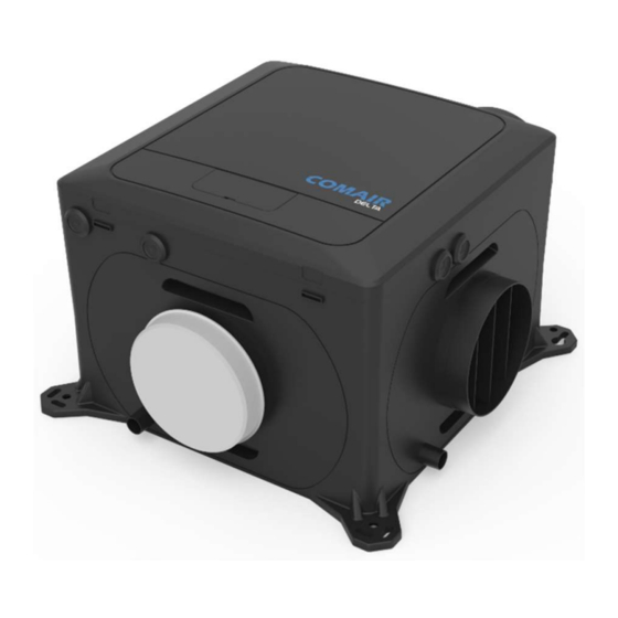
Comair Delta 52YF
Comair Delta 52YB
DOWNLOAD THE IOS APP HERE:
9099001095
9099001282
IPX2
Advertisement

Related Manuals for COMAIR Delta 52YF

Summary of Contents for COMAIR Delta 52YF
- Page 1 Reference Comair Delta 52YF 9099001095 Comair Delta 52YB 9099001282 IPX2 PLEASE READ INSTRUCTIONS IN CONJUNCTION WITH THE ILLUSTRATIONS. PLEASE SAVE THESE INSTRUCTIONS DOWNLOAD THE ANDROID APP HERE: DOWNLOAD THE IOS APP HERE:...
- Page 2 Installation and Wiring Instructions for the Delta Extract Fans. IMPORTANT: READ THESE INSTRUCTIONS BEFORE COMMENCING THE INSTALLATION Do not install this product in areas where the following may be present or occur: Excessive oil or a grease laden atmosphere. ...
- Page 3 (Internal) (Internal) Input Delta 52YF Delta 52YB The units can be precisely programmed to determine how they respond to changes in sensor values or the status of the various signal inputs. The units will run at a Normal flowrate until a sensor or input change causes it to change speed.
- Page 4 Pressure vs Flow curves Figure 2 Comair Delta 52YF 9099001095 Comair Delta 52YB 9099001282...
- Page 5 INSTALLATION Position the unit, taking into consideration the position of the rooms to be ventilated, the exhaust position and the electrical services. Ensure there is adequate access for installation and maintenance. The unit can be mounted horizontally or vertically. It can be positioned on the floor, wall or ceiling. If the unit is sited in the heated void of the dwelling a condensate drain should not be necessary.
- Page 6 Figure 4 Figure 5...
- Page 7 Base mounted Installation with ducting radiating out horizontally. Figure 6 Vertically mounted Installation with the exhaust spigot at top. The electrical connections must come out of the bottom of the unit in order to maintain the water ingress protection. Figure 7...
- Page 8 iii. Ceiling mounted Installation with ducting radiating out horizontally. Figure 8 WIRING WARNING: THE UNIT AND ANCILLARY CONTROL EQUIPMENT MUST BE ISOLATED FROM THE POWER SUPPLY DURING THE INSTALLATION / OR MAINTENANCE. THIS UNIT MUST BE EARTHED. To remove the cover, use a coin or similar; depress the retaining tabs via the slots in the side of the unit.
- Page 9 CONNECTION DIAGRAM Figure 9 Main power connections Low voltage A: Main power connections connections, if fitted The LS1, LS2 and NS terminals are electrically isolated. Note: Neutral link between 2 & 6 should be removed if different RCD protection circuits are used for mains power a &...
- Page 10 B: Low voltage connections For best performance use 4-core, low voltage, twisted pair, telecoms type cable for accessories. Figure 11 Position Label Description Action 5V Output, Max 250mA RS485 communication to wired accessories. Data RS485 Data connection (B, C) if available. Data The 5V and Ground connections are available on all units.
- Page 11 Figure 14 RF868 Wireless inputs Units that contain a Wireless receiver can be paired with compatible sensors, these can be mains or battery powered depending on the sensor. A maximum of 15 wired and wireless sensors can be connected to a single unit. Pairing sensors To pair the unit with a wired or wireless sensor: Press the Mode button to turn on the display.
- Page 12 Example - LED Fault Indicator Connection Example - LED Boost Indicator Connection Low Voltage Switch’s – Boost & Low Speed FEATURE DESCRIPTIONS If compatible, the unit can be controlled via the Bluetooth linked App. Comfort mode If Comfort mode is enabled the unit will behave as follows to all LS inputs: Trigger Action LS input active less than 5 minutes...
- Page 13 Delay On A delay can be set so that the unit will not respond to an input until after the set delay has elapsed, applies to LS inputs only. Overrun Timer The unit can be set to run for a defined period after the input is removed, applies to LS inputs only. Humidity –...
- Page 14 Wireless units can be commissioned via the Bluetooth connected App. Links to the App are shown on the cover page of this manual. The App must be installed before a connection to the unit is possible. Bluetooth Pairing To enable Bluetooth pairing on the unit: Press the Mode button to turn on the display Press and hold the Mode button until the LED illuminates solid Blue Release the mode button, the LED will flash Blue to indicate that it is in pairing mode.
- Page 15 User Configurable Parameters Function Display Selections Default text Low speed 1 to 97% motor speed Normal speed 2 to 98% motor speed Boost speed 3 to 99% motor speed Purge Speed 4 to 100% motor speed 100% Live switch 1 Low, Boost or Purge speed Live switch 2 Low, Boost or Purge speed...
- Page 16 MEV Unit – Internal sensor Step 1 can be done by either Exposure method or Measurement method, the baseline step 2 is actioned once either step 1 options are complete. Exposure method step 1 Exposure method assumes that the outside CO concentration is 400 PPM in the rooms in which the MEV extracts air from, the Rooms must be well ventilated by opening any external windows and doors for 10 to 15 minutes.
- Page 17 SERVICING & MAINTENANCE WARNING: THE FAN AND ANCILLARY CONTROL EQUIPMENT MUST BE ISOLATED FROM THE POWER SUPPLY DURING MAINTENANCE. Individual faulty parts should not be replaced due to complexity of assembly. Only the full scroll assembly is replaceable. To remove the scroll assembly, isolate the power, then use a coin or similar to depress the cover retention clips and remove the cover.
- Page 18 Product Fiche Name: Comair Comair Delta 52YF Comair Delta 52YB Model ID (Stock Ref.) 9099001095 9099001282 SEC Class SEC Value ('Average') -27.2 SEC Value ('Warm') -11.7 SEC Value ('Cold') -54.3 Label Required? (Yes/No=Out of scope) Declared as: RVU or RVU/UVU...
- Page 19 Disposal This product should not be disposed of with household waste. Please recycle where facilities exist. Check with your local authority for recycling advice. The Guarantee Only applicable to products installed and used in Belgium, the Netherlands or Germany. For more information about the warranty outside these countries, please contact your local supplier.
- Page 20 Reference Comair Delta 52YF 9099001095 Comair Delta 52YB 9099001282 IPX2 LEES DEZE INSTRUCTIES IN COMBINATIE MET DE AFBEELDINGEN. BEWAAR DEZE INSTRUCTIES DOWNLOAD DE ANDROID-APP HIER: DOWNLOAD DE IOS-APP HIER:...
- Page 21 Installatie- en bedradingsinstructies voor de DELTA afvoerventilatoren. BELANGRIJK: LEES DEZE INSTRUCTIES VOOR U BEGINT MET DE INSTALLATIE Installeer dit product niet in omgevingen waar de volgende omstandigheden aanwezig zijn of kunnen optreden: Klimaat met uitzonderlijk veel olie of vet. ...
- Page 22 Geschikt voor Bluetooth v4.1 De Bluetooth- en RF-radiovarianten beschikken over het RED-certificaat: Nr. 0051-RED-0011 REV. 0 Zirconia-draadloos: -14dBm EIRP nominaal 868MHz. De fabrikant waarborgt dat dit type Bluetooth radio- en 868MHz radio-apparatuur overeenstemt met de RED-richtlijn 20145/53/EU De volledige tekst van de EU-conformiteitsverklaring kan worden gevonden op het volgende URL-adres: https://www.ventilair.nl/media/files/Conformiteitsverklaring_Comair_Delta_NL.pdf...
- Page 23 (intern) (intern) ontvanger ingang Delta 52YF Delta 52YB De units kunnen nauwkeurig worden geprogrammeerd om te bepalen hoe ze reageren op wijzigingen in de sensorwaarden of de status van de diverse signaalingangen. De units werken met een normaal luchtvolume, dat wordt aangepast wanneer een signaal wordt gegeven door een sensor of ingang. In het geval van 230V-ingangen, digitale, analoge, bedrade en draadloze ingangen wijzigen de units stapsgewijs hun snelheid, tot het gevraagde niveau is bereikt.
- Page 24 Druk- en luchtvolumegrafieken Afbeelding 2 Comair Delta 52YF 9099001095 Comair Delta 52YB 9099001282...
- Page 25 INSTALLATIE Monteer de unit, rekening houdend met de locatie van de te ventileren ruimtes, de positie van de afblaas, en de elektrische voorzieningen. Zorg voor voldoende ruimte voor installatie en onderhoud. De unit kan zowel horizontaal als verticaal worden geïnstalleerd. Hij kan worden geplaatst op de vloer, de muur of aan het plafond.
- Page 26 Om de luchtdichtheid te garanderen, bevestig de luchtkanalen bij installatie van de FLX Ø90 mm- versie, zodanig dat in de klikdelen telkens 3 klikken gehoord worden. Afbeelding 6 Afbeelding 7...
- Page 27 Horizontale installatie met horizontaal geplaatste luchtkanalen. Afbeelding 8 Verticale installatie met afvoerluchtkanalen aan de bovenkant. De elektrische aansluitingen moeten aan de onderkant van de unit komen, ter bescherming tegen binnendringend water. Afbeelding 9...
- Page 28 Installatie aan het plafond met horizontaal geplaatste luchtkanalen. Afbeelding 10 BEDRADING WAARSCHUWING: DE UNIT EN BIJHORENDE REGELAPPARATUUR MOETEN TIJDENS INSTALLATIE OF ONDERHOUD VAN DE VOEDING WORDEN GESCHEIDEN. DEZE UNIT MOET WORDEN GEAARD. Druk de lipjes via de sleuven aan de zijkant van de unit in om het voorpaneel te verwijderen. Zet de stroom uit en sluit een geschikte voedingskabel, voldoende afgezekerd, aan op het schroefklemmenblok.
- Page 29 BEDRADINGSSCHEMA Afbeelding 11 Voedingsklemmen Laagspanningsklemmen (afhankelijk van type) A: Hoofdvoedingsaansluitingen De LS1-, LS2- en NS-aansluitklemmen (A) zijn elektrisch gescheiden. Als de LS-aansluitingen gebruikt zijn, moet de NS-aansluitklem worden gebruikt. Dit is mogelijk met een jumperverbinding of specifieke aansluiting op de nulgeleider. Deze unit is uitsluitend voor functionele doeleinden voorzien van een aarding.
- Page 30 B: Aansluitingen voor laagspanning Bij voorkeur wordt een 4-aderige UTP/STP-datakabel gebruikt voor de aansluiting van accessoires. Afbeelding 13 Positie Label Omschrijving Handeling 5V Uitgang, Max. 250mA RS485-communicatie met bedrade accessoires. Data RS485 Dataverbinding (B, C), indien aanwezig. Data Alle units beschikken over 5V- en aardaansluitingen. Aarde Gemeenschappelijke digitale Ga naar Boost (Hoog)-snelheid...
- Page 31 Afbeelding 16 RF868 draadloze ingangen Units met een draadloze ontvanger kunnen worden gekoppeld met bijhorende sensoren en schakelaars, die, afhankelijk van het type, via de elektriciteit of door een batterij worden gevoed. In totaal kunnen tot maximaal 15 bedrade en draadloze accessoires op 1 unit worden aangesloten. Sensoren koppelen De unit met een bedrade (RS485) of draadloze (RF868) sensor koppelen: Druk op de knop Mode om het display in te schakelen.
- Page 32 Voorbeeld - Aansluiting LED-foutindicator Voorbeeld - Aansluiting led-boostindicator Laagspanningsschakelaars - Boost en lage snelheid Lage snelheid...
- Page 33 FUNCTIEBESCHRIJVINGEN Draadloze units kunnen via bluetooth worden bediend via de Comair Connect app. Comfortmodus Als de unit in de comfortmodus is ingesteld, reageert deze als volgt op alle LS-ingangen: Activering Handeling Geen handeling (blijft werken op de normale LS-ingang minder dan 5 minuten geactiveerd...
- Page 34 De 3-cijferige pincode bevat de letters A tot F en de cijfers 0 tot 9, en is standaard ingesteld op LoC. * Als externe CO - of vochtsensoren via de RS485 zijn aangesloten, dan hebben deze voorrang op de interne sensoren. De waarde van deze sensoren wordt ook op de unit weergegeven, in plaats van die van de interne sensor.
- Page 35 Door gebruiker instelbare parameters Schermtekst Functie Keuzes Standaard Lage snelheid 1 t/m 97% van de ventilatorsnelheid 10% / 20% Normale snelheid 2 t/m 98% van de ventilatorsnelheid Hoog-snelheid 3 t/m 99% van de ventilatorsnelheid Snelheid voor Maximaal 4 t/m 100% van de ventilatorsnelheid 100% Live schakelaar 1 Lage snelheid, Hoge- of Maximale snelheid...
- Page 36 1. MEV-unit - interne sensor Kalibratiestap 1 kan worden uitgevoerd via de blootstellingsmethode of de meetmethode. Kalibratiestap 2 kan worden uitgevoerd zodra een van de twee opties van stap 1 is voltooid. 1.1. Stap 1 met de blootstellingsmethode De blootstellingsmethode gaat ervan uit dat de CO2-concentratie buiten gelijk is aan 400 ppm in de ruimtes waarin de MEV-unit lucht afzuigt.
- Page 37 2.2 Stap 2 van de kalibratie Wanneer de ruimtesensor met het systeem is gekoppeld, licht de status-LED groen op wanneer de knop wordt ingedrukt. In deze toestand moet de knop worden ingedrukt en vastgehouden (8 seconden) tot de status-LED oranje oplicht. De knop moet vervolgens worden losgelaten en de status-LED knippert vervolgens oranje om het begin van het kalibratieproces aan te geven.
- Page 38 ONDERDELEN EN ACCESSOIRES Neem contact op met uw verdeler voor onderdelen en accessoires, zie de informatie op de laatste pagina van deze handleiding. Compatibele accessoires Type unit Wireless Draadloos Type regelaar Bedraad RS485 RF868 Temperatuur-/vochtsensor (batterij) Temperatuur-/vochtsensor (230V) ...
- Page 39 Productfiche Naam: Comair Comair Delta 52YF Comair Delta 52YB Model-ID (referentienr.): 9099001095 9099001282 SEC-klasse SEC-waarde ('gemiddeld') -27,2 SEC-waarde ('warm') -11,7 SEC-waarde ('koud') -54,3 Label nodig? (ja / nee = buiten bereik) Aangegeven als: RVU of NRVU/UVU of RVU/UVU Aandrijfsnelheid Met meerdere snelheden...
- Page 40 Afvoer Dit product mag niet met het gewone huisvuil worden afgevoerd. Indien mogelijk recyclen. Controleer bij uw gemeente voor advies over recyclen. De garantie Alleen van toepassing op in België, Nederland of Duitsland geïnstalleerde en gebruikte producten. Neem contact op met uw plaatselijke leverancier voor meer informatie over de garantie buiten deze landen.
Need help?
Do you have a question about the Delta 52YF and is the answer not in the manual?
Questions and answers